 |
|||
|
|
|||
|
|
|||
| ||||||||||
|
|
 *TM 9-2815-213-34
Governor-cutoff rpm ....................... 3020 3040
Set-p.s.i. @ max rpm ..................... 40 @ 3250
Throttle leakage--cc ....................... 35
Idle speed-p.s.i. @ rpm ................... 22 @ 600
Manifold pressure p.s.i. @ rpm ....... 227 @ 3000
Check point 1 p.s.i. @ rpm.............. 165/173 @ 200
Check point 2 p.s.i. @ rpm.............. 117/125 @ 2000
Weight assist p.s.i. @ rpm .............. 46/54
800
Weight assist setting ...................... 890/910
Gear pump size............................... 3/4
Idle plunger code No ......................
40
Torque spring-part No ..................... 142698
Torque spring-color code ................ WHITE-BROWN
Torque spring--hims ....................... NONE
Governor spring-part No ................. 147292
Governor spring--color code ........... BROWN
Governor weight-part No................. 107261
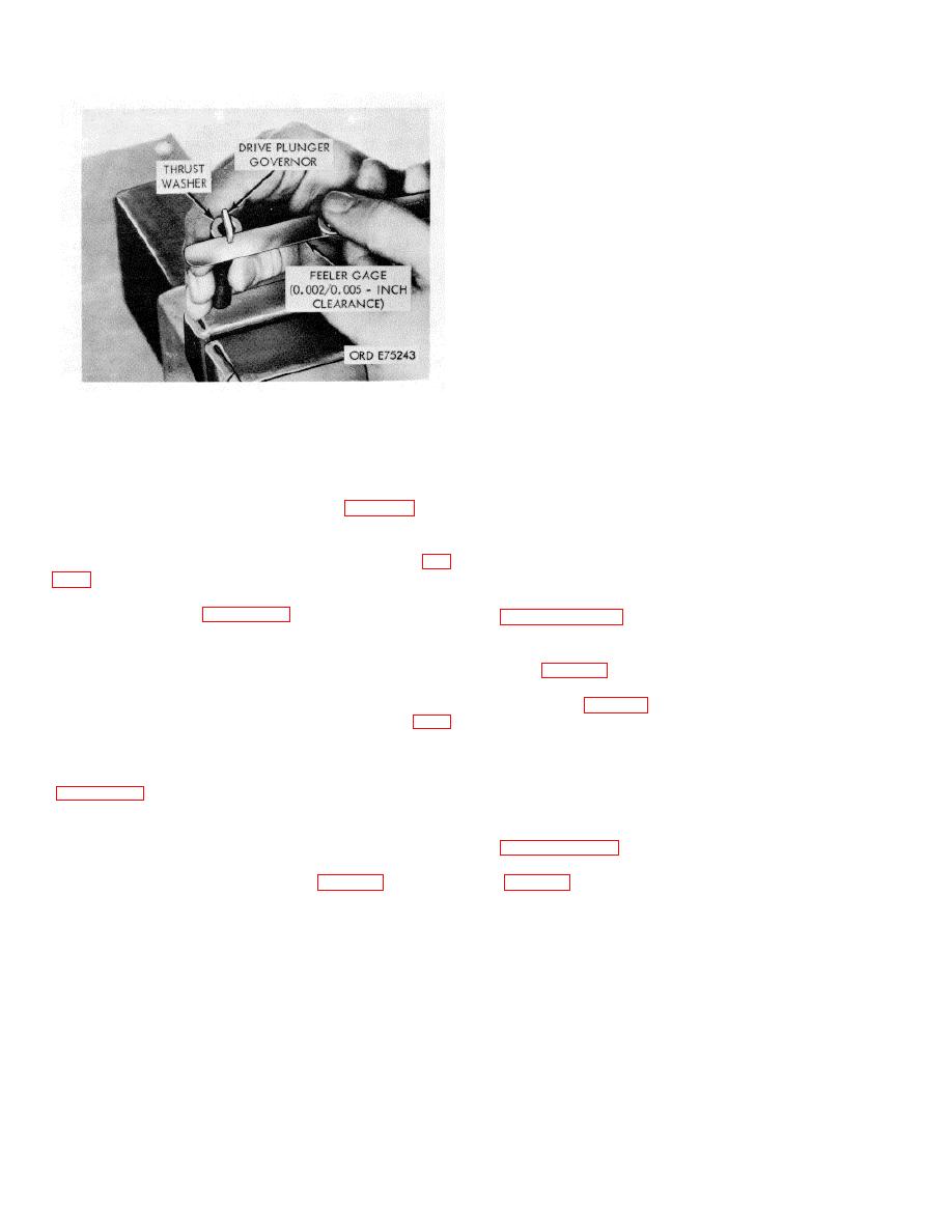
Figure 3-89. Thrust washer-drive plunger governor
Injector-part No ............................... BM97421
clearance.
Injector-flow code ........................... 117
CAUTION
Piston-part No ................................ 172580
When installing governor weight assembly, do not press
Camshaft-part No ........................... 155500
against weights. Press against center of weights carrier
c. Test Fuel. Fill fuel pump test stand with
shaft.
authorized fuel.
(1) Using oil seal assembly tool (35, fig. B-28) and
d. Precalibration Tests. The precalibration tests
suitable press, install first oil seal into cover with lip
(para. 3104.b., 3-104.d.) are to be performed to check
toward inside of cover. Then, install second oil seal into
porosity of fuel pump housing, excessive leakage, or low
reverse side of cover with lip toward inside of cover (fig.
gear pump output, prior to calibration on the fuel pump
test stand.
(2) Assemble remaining components in reverse
e. Mounting Pump For Calibration. Refer to
order of disassembly (para. 3-102.a. (3)).
NOTE
f. Fuel Pump Run-.In.
When weight assist plunger is installed in
(1) Completely open the fuel pump manual override
weight carrier assembly it must protrude
knob (fig. 3-73).
0.840/0.860 inch.
(2) Open throttle to maximum position and secure
f. Fuel Pump Damper Assembly. Assemble
with spring (fig. 3-82).
damper assembly in reverse order of disassembly (para
(3) Start test stand motor and run pump at 500 rpm.
3-102.a. (2)).
(4) If pump is newly rebuilt or has been
g. Fuel Shut-Off Solenoid Valve Assembly.
disassembled and reassembled, run at slightly overrated
Assemble solenoid valve in reverse order of disassembly
speed of 3000 rpm for 5 minutes to flush, allow bearings
and seals to seat, and to purge air from system.
Ring, and gaskets for assembly.
(5) Check pump fuel flow in the flow meter for air. If
air is present, correct the leak before continuing. Refer to
3-107. Fuel Pump Test and Calibration
a. General. PT type G fuel pump is tested and
(6) Check main throttle shaft for proper shimming
calibrated on the fuel pump test stand (fig. 3-80).
b. Fuel Pump Test and Calibration Data.
(7) Periodically check the fuel to insure that it is 80
Engine model .................................. V8 300
to 100 degrees Fahrenheit and clean of all foreign
Pump code ...................................... 50CR3000
matter.
HP C rpm (sea level) ....................... 300 @ 3000
NOTE
Fuel rate-lb hr min/max ................... 119/124
If visual inspection or run-in check indicate
Engine fuel pressure min/max ......... 215 235
internal problems perform inspection of the
Flow meter-lb hr @ rpm................... 560 @ 3000
disassembled pump.
3-48
|
|
Privacy Statement - Press Release - Copyright Information. - Contact Us |