 |
|||
|
|
|||
|
Page Title:
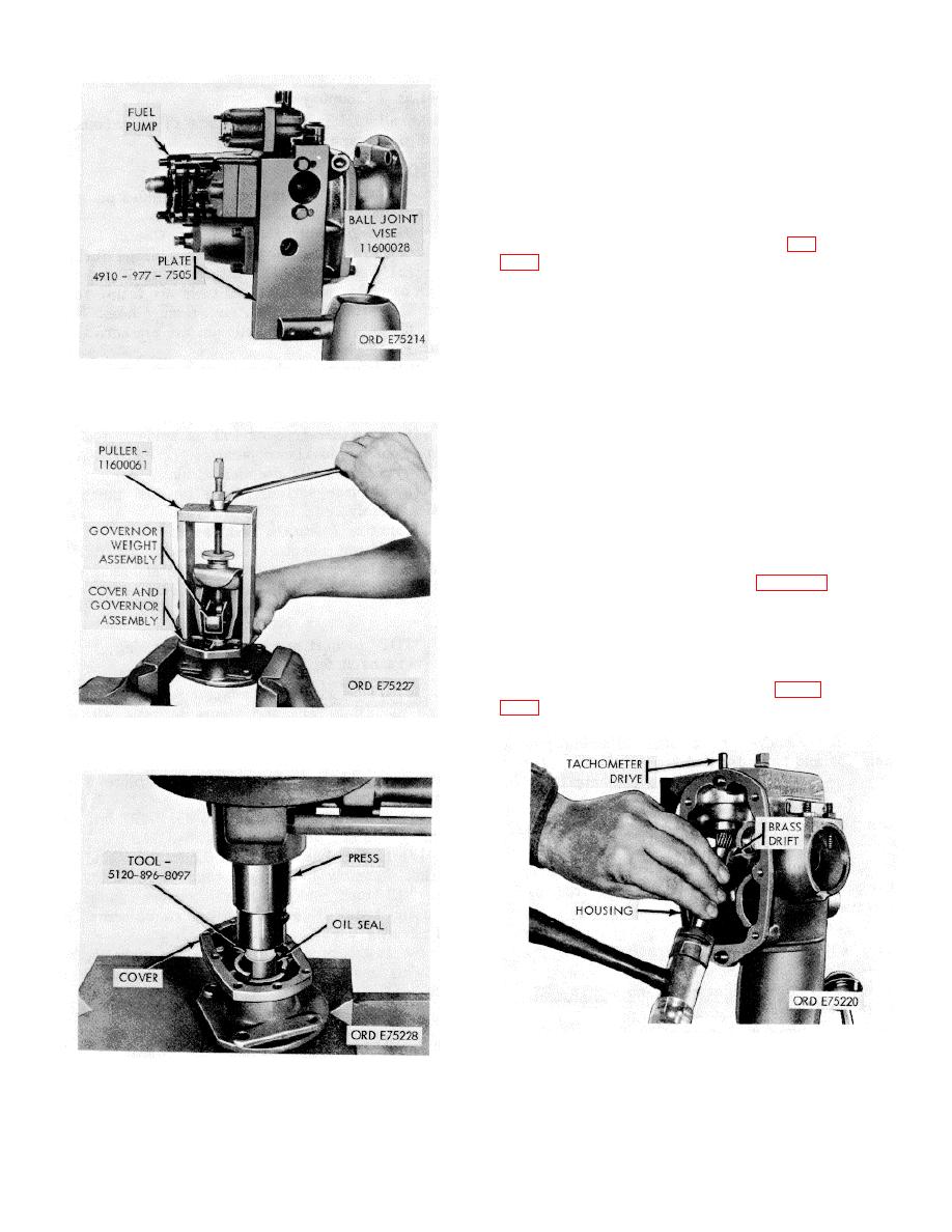
Figure 3-74. Mounting plate and ball joint vise installation |
|
||
| ||||||||||
|
|
 *TM 9-2815-213-34
(14) and lockwashers (9) securing gear assembly
(1) to pump housing. Remove gasket (2).
(b) Separate cover (15) and housing
from two dowels (4) to release two shafts (6 and
7) two gears (5). Discard gasket (8).
(c) Remove ring dowels (3) from hous-
ing.
(d) Remove inlet adapter (12) and ball
check valve elbow (11) from cover.
(a) Cut seal wire (33) and remove cap-
screw seal (34).
(b) Remove two capscrews (32), two cap-
screws (36), four lockwashers (31) and four flat
washers (30) securing assembly to pump hous-
ing. Discard gasket (28).
(c) Remove spring pack assembly from
Figure 3-74. Mounting plate and ball joint vise
housing barrel.
installation.
(d) Remove snap ring (27) from guide
and clip assembly (22).
(e) Remove spring retainer (26), high
speed spring shims (25), and high speed spring
(24).
(f) Remove idle adjusting screw (23),
adjusting screw washer (21), idle speed spring
(20), and plunger (19).
(g) Remove pipe plug (35) from cover.
(a) Remove two slotted-head screws (3)
securing tachometer cable drive adapter (1) and
cap (2) to pump housing.
(b) Remove adapter, cap, gasket (2), and
shaft seal (5). Discard gasket.
(c) Using a brass drift, as shown in figure
Figure 3-75. Governor weight assembly removal/
installation.
Figure 3-77. Tachometer drive assembly-
removal/installation.
Figure 3-76. Governor shaft oil seals-
removal/installation
3-39
|
|
Privacy Statement - Press Release - Copyright Information. - Contact Us |