 |
|||
|
|
|||
|
Page Title:
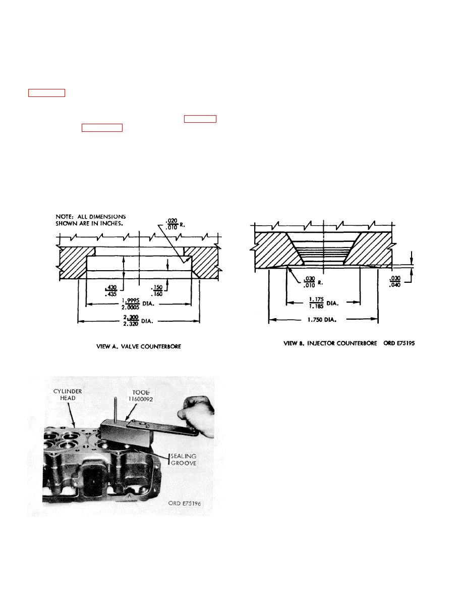
Figure 3-36. Valve and injector counterbore dimensions. |
|
||
| ||||||||||
|
|
 TM 9-2815-213-34
(2) Measure head height using micrometer or
in same direction as cutter; tighten assembly in place.
vernier calipers; dimensions must not exceed
(4) Rotate cylinder head and install regrooving
4.4890/4.4990 inches.
cutter in injector bore (fig. 347).
(3) Restore counterbore and pocket depth at
(5) Check position of stop in tool holder to make
valves and shallow counterbore area around injector port
certain it will not contact water hole during regrooving
operation.
indicated contours.
(6) Adjust regrooving cutter so it protrudes
b. Regroove Cylinder Head. If cylinder head has
0.006/0.008 inch below stop. Rotate tool clockwise to cut
grooves. Do not rotate counterclockwise.
been resurfaced, regroove with grooving tool (33, fig. B-
28), as shown in figure 3-37.
(1) Select scrapped injector, preferably one with
CAUTION
class "0" plunger bore and injector cup. Cut off cup to
Do not attempt to cut deeper than cutter
expose plunger bore, to keep cup seal area intact.
groove depth or grooves will not form in
(2) Install injector in cylinder head and tighten
head. Groove lands should be
30/35 foot-pounds torque.
0.010/0.015 inch wide and must not
(3) Select correct tool spacer block, 0.940 inch
extended above head surface
thick. Assemble the regrooving tool, positioning largest
pilot pin so it protrudes downward
Figure 3-36. Valve and injector counterbore dimensions.
Grind Valves.
c.
(1) Wet grind valve from horizontal to exactly 30
degree angle.
(2) Inspect rim thickness after grinding as shown
in figure 332; if rim is less than 1/16 inch, valve is not
suitable for use and must be replaced.
(3) Check valve in reamed guide and against
newly ground valve seat face. Pencil mark valve face and
drop into position and rotate 10 degrees. A good seat will
be indicated if all pencil marks are broken. If pencil
marks are not broken either valve seat or valve refacing
tools have not been properly adjusted; final check should
be made with vacuum tester.
3-68. Assembly
a. Valve Guide.
Figure 3-37. Cylinder head regrooving.
3-19
|
|
Privacy Statement - Press Release - Copyright Information. - Contact Us |
