 |
|||
|
|
|||
|
Page Title:
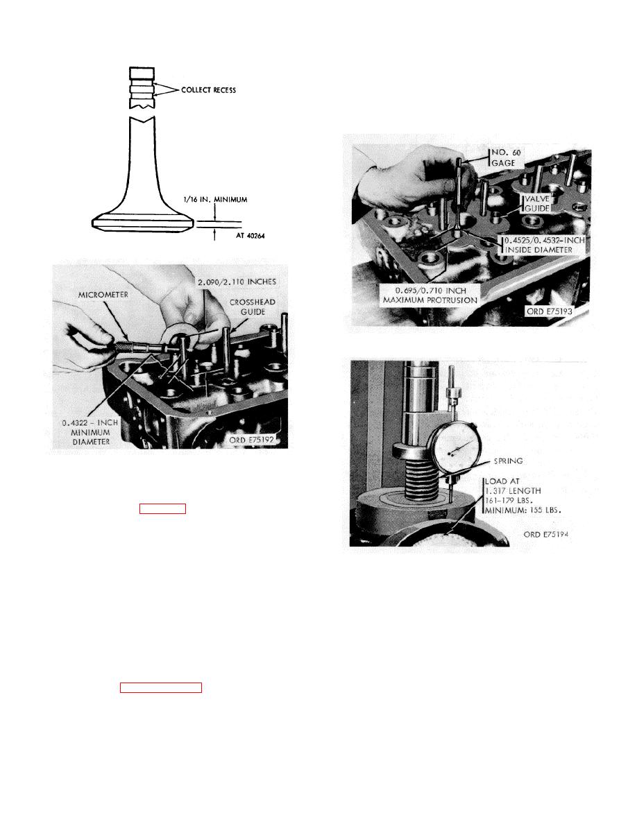
Figure 3-32. Valve head and collet check. |
|
||
| ||||||||||
|
|
 TM 9-2815-213-34
NOTE
A 1/32 inch spacer may be used under
valve spring when insert and valve have
been refaced.
(2) Replace springs if load is less than indicated
under "wear limits" at required compressed length.
Figure 3-32. Valve head and collet check.
Figure 3-34. Valve guide check
Figure 3-33. Crosshead guide cheek.
(5) Check valve guide protrusion to limit of
0.695/0.710 inch.
NOTE
Weak valve springs may cause flutter
Figure 3-35. Valve spring test.
which results in excessive wear on both
valve and seat. Valve flutter interferes
3-67. Repair
with valve timing and may cause valve to
a. Resurface Cylinder Head. Resurface head only
strike the piston head. Weak springs
if it has been scratched, etched, or worn unevenly at
may also cause valve warping, cracking
point of contact with gasket sealing areas.
and breaking.
(1) Remove a maximum of 0.006 inch of
material.
(1) Using a spring tester capable of very
NOTE
accurate measurements of spring lengths and applied
The gasket surface should not deviate
load, check springs against limits speciflied in repair and
from a true plane b, mote than 0.004-
rebuild standards, paragraph 3-183.
inch.
3-18
|
|
Privacy Statement - Press Release - Copyright Information. - Contact Us |