 |
|||
|
|
|||
|
Page Title:
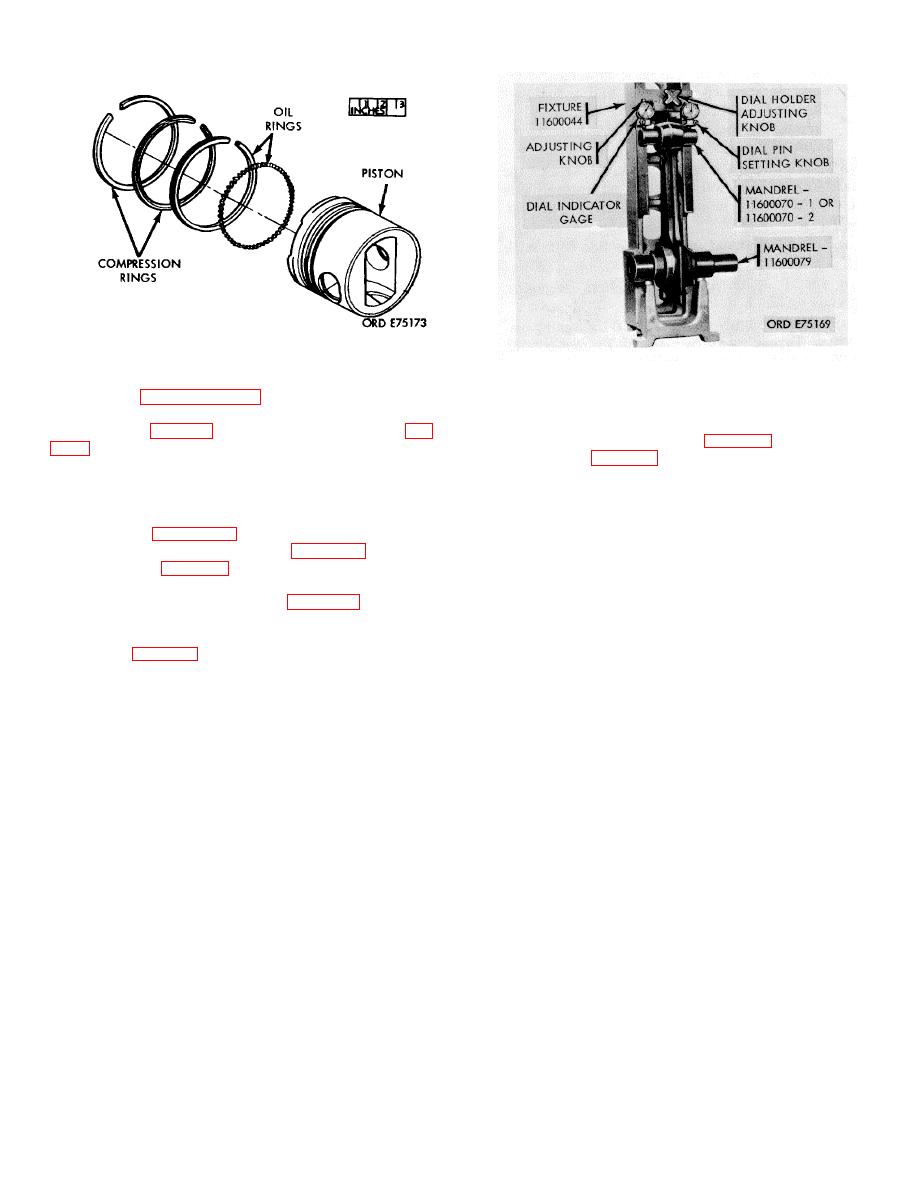
Figure 3-9. Piston and ring assembly. |
|
||
| ||||||||||
|
|
 *TM 9-2815-213-34
Figure 3-9. Piston and ring assembly.
.
Figure 3-10. Connecting rod check.
not exceed wear limits shown in repair an build
standards in paragraph 3-178. f. Check connecting rod
B28) into connecting rod bore. Tighten mandrel to snug
piston pin and bearing bore alignment, rod twist, and
fit.
rod centerline (fig. 3-10) in rod checking fixture (40, fig.
(2) Install mandrel (22, fig. B-28) used without
bushing or (21, fig. B-28) used with bushing into piston
Select a new rod that has been checked for correct
pin bushing bore.
absolute length. (Production rods vary from 8.192/8.194
(3) Install rod with mandrels in fixture Note
inches in length.)
reading, rotate rod 180 degrees, and note reading
(2) Assemble cap to rod and tighten nuts to
again. Total cumulative readings of each dial on fixture
proper torque (para. 3-186).
must not exceed 0.004 inch with piston pin bushing
(3) Insert mandrel (22, fig. B-28) without
installed or 0.008 inch with-out piston pin bushing
bushing or (21, fig. B-28) used bushing into piston pin
installed.
bushing bore.
h. Check rod twist with a feeler gage between
(4) Insert mandrel (20, fig. B-28) crankpin
piston pin mandrel and dial holding plate. Twist must not
bushing bore. Tighten mandrel in to snug fit.
exceed 0.010-inch with bushing installed or 0.020-inch
(5) Position rod with mandrels installed into
without bushing.
fixture (40, fig. B-28).
i. Check rod centerline as follows:
(6) Move dial holders so dial pins seat on
(1) Attach dial indicator gage to fixture (fig. 3-
piston pin bore mandrel. Turn dial indicator gages back
10) so that it will contact the milled surface of piston pin
to zero indication.
end of rod.
(7) Remove rod with mandrels installed from
(2) Slide crankpin end of rod sideways to
fixture, rotate rod 180 degrees and reinstall in fixture
contact checking fixture on same side that dial indicator
with connecting rod mandrel at top.
is mounted.
(8) Turn dial indicator adjusting screws until
(3) Adjust indicator gage to zero reading. Turn
dial pins seat on connecting rod mandrels. Note reading
Rod 180 degrees and repeat step (2) above. Dial
of dial indicators. Divide reading in half and adjust each
indicator reading must not exceed 0.015 inch.
dial indicator gage accordingly.
j. Check connecting rod bolts, bolt holes, and bolt
(9) Remove mandrels from connecting bores.
pads as follows:
g. Check rod alignment as follows:
(1) Bolt head must rest squarely on milled
surfaces of rod.
NOTE
(2) With rod bolt in connecting rod and cap,
measure bolt length without torque applied,
then
Measurements taken directly from dial
measure bolt length with it torqued to 105/115 ft lbs. If
indicator indicate comparative length
bolt length increases over 0.015 inch it must be
and misalignment of bores.
discarded.
(3) Discard all bolts and nuts that have
(1)
Install connecting rod mandrel (20,fig
distorted threads.
(4) Check bolt hole diameter, if it exceeds
0.5643 inch, discard rod.
3-6
|
|
Privacy Statement - Press Release - Copyright Information. - Contact Us |