 |
|||
|
|
|||
|
|
|||
| ||||||||||
|
|
 c. Clutch Cover. Replace the clutch cover
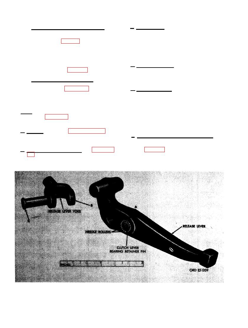
(4) Release levers and needle rollers. In-
(B-2) when cracked or warped. Repair minor
thread damage using a used tap. Replace the
against limits specified in repair and re-
clutch cover when screw holes are elongated
build standards (par. 298). Inspect re-
or warped. Replace the clutch cover when
lease levers for cracks and 152 bearing
rollers (B- l-b) for roughness and wear.
pressure spring seats are cracked or contain
indentations that will affect spring tension.
Inspect the four release lever pins (B-
I-a) and the four yoke pins (B- l-d)
d. Pressure Springs. Replace the pressure
against limits specified in repair and
springs (B-6) when distorted, cracked, or in a
rebuild standards (par. 298).
set condition. Replace any pressure springs that
do not have the correct free length.
(5) Driven member assembly. Inspect
driven member assembly following in-
structions for figure '91, excluding
e. Pressure Plate. Replace the pressure
plate (B-1-c) when cracked, warped, or when
step C.
the pressure plate clutch facing surface is
burned or scored beyond a 1/16-inch resur-
250. REPAIR
facing limit. Regrind a scored or slightly
cracked pressure plate using a surface grinder.
Note. The key letters shown below in paren-
theses refer to figure 456 except where other-
Do not grind surface more than 1/16-inch to
achieve a good surface. If more grinding is
wise indicated.
required, replace the pressure Plate.
a. General. Refer to paragraph 154 for
f. Release Levers and Needle Rollers. Re-
general repair instructions. Special repair in-
place any release levers (B-1-e) that do not
structions are listed below.
meet limits specified in repair and rebuild
standards (par. 298). Replace worn or damaged
b. Driven Member Assembly. Refer to para-
needle rollers in sets only. Replace worn re-
graph 67b and c for repair of the driven mem-
lease lever and yoke pins.
ber assembly (A).
YOKE USING BEARING RETAINING PIN.
292
|
|
Privacy Statement - Press Release - Copyright Information. - Contact Us |
