 |
|||
|
|
|||
|
|
|||
| ||||||||||
|
|
 sandpaper and remove all traces of dust with
compressed air.
Caution: Do not spin ball bearings (CC) with
compressed air or attempt cleaning them with
dry- cleaning solvent. Bearings are prelubri-
cated and sealed. Refer to TM 9-214 for care
and maintenance of ball bearings.
c. Brushes. Clean brushes (EE) with a clean,
dry- cloth only. Do not permit dry-cleaning sol-
vent to contact the brushes.
d. Insulated Choke and Capacitor. Wipe the
insulated choke (L) and capacitor (M) with a
clean, dry cloth. Do not allow dry-cleaning
solvent to contact the insulated choke and
capacitor.
e. Brush Holder and Insulator. Clean brush
holder (W) and insulator (V) with a cloth
dampened with dry- cleaning solvent. Dry thor-
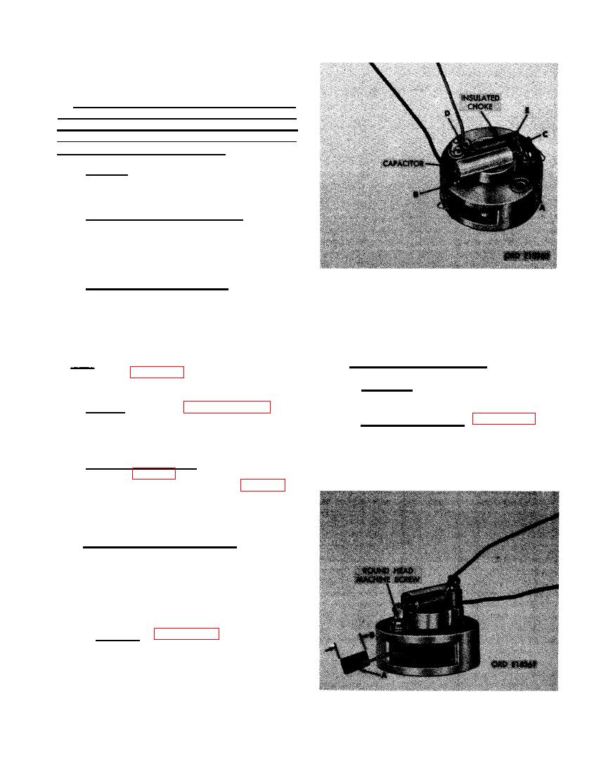
CAPACITOR AND INSULATED CHOKE.
oughly with compressed air.
from terminal. (E) Remove insulated
choke and red wire.
d. Brushes and Brush Springs.
Note. The key letters shown below in paren-
theses refer to figure 431 except where other-
wise indicated.
(1) Inspection. Inspect brushes (EE) and
brush springs (FF) for cracks or breaks.
a. General. Refer to paragraphs 153 and
154 for general inspection and repair instruc-
(2) Check brush length. Figure 434. (A)
tions. Special inspection and repair instructions
Pull brushes out of brush holders.
are listed in paragraphs b through f below.
(B) Measure brush length. New brushes
--
are 3/8- inch long. Serviceable brushes
b. Relief Valve Housing. Inspect the relief
should be at least 5/16-inch long.
valve ball (K, fig. 432) and the ball seating
area in the relief valve housing (H, fig. 432)
for scores, scratches, and wear patterns. Re-
place parts when any of the above conditions
exist.
c. Insulated Choke and Capacitor.
(1) Inspection. Inspect the insulated choke
and capacitor (M) for frayed or
cracked insulation. Test the insulated
choke for continuity using a continuity
tester. Remove either if defective.
(2) Removal. Figure 433. (A) Unsolder
capacitor and insulated choke leads
from terminal. (B) Unsolder remaining
capacitor lead and black wire lead from
terminal. (C) Remove capacitor and
black wire. (D) Unsolder remaining in-
sulated choke lead and red wire lead
275
|
|
Privacy Statement - Press Release - Copyright Information. - Contact Us |