 |
|||
|
|
|||
|
Page Title:
FIGURE 235. REMOVING OR INSTALLING OIL COOLER WATER INLET TUBE. |
|
||
| ||||||||||
|
|
 and remove tube. Remove hose from
tube. (D) Remove and discard oil cooler
water inlet tube gasket.
OIL COOLER WATER INLET TUBE.
(2) Figure 236. (A) Remove twelve 1/4-
inch plain nuts and 1/4-inch lock
washers securing oil cooler cover to
oil cooler and oil filter housing. (B) Re-
move oil cooler cover. (C) Remove and
(4) Figure 238. (A) Remove and discard
discard oil cooler cover gasket.
two 7/8 id x 1/8 thk preformed pack-
ings. (B) Remove one 3/8 x 5-1/8 self-
locking bolt and 3/8-inch flat washer.
(C) Remove sixteen 3/8 x 7/8 cap
screws and 3/8-inch flat washers se-
curing oil cooler and oil filter housing
to cylinder and crankcase. (D) Remove
oil cooler and filter housing from crank-
case.
OIL COOLER COVER.
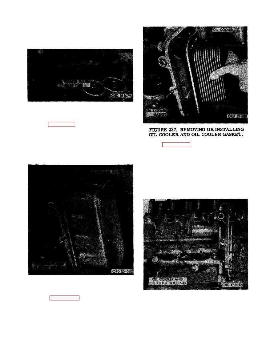
(3) Figure 237. (A) Remove oil cooler.
(B) Remove and discard oil cooler gas-
OIL COOLER AND OIL FILTER
ket.
HOUSING ASSEMBLY.
155
|
|
Privacy Statement - Press Release - Copyright Information. - Contact Us |
