 |
|||
|
|
|||
|
Page Title:
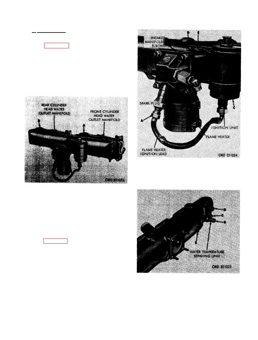
FIGURE 175. REMOVING OR INSTALLING CYLINDER HEAD WATER OUTLET MANIFOLDS |
|
||
| ||||||||||
|
|
 b. Disassembly. Disassemble the intake
manifold assembly as follows.
(1) Figure 175. (A) Loosen the two 1-5/8-
inch hose clamps and remove front
cylinder head water outlet manifold from
intake manifold. (B) Loosen the two
1-5/8- inch hose clamps and remove
rear cylinder head water outlet mani-
fold from intake manifold.
INTAKE MANIFOLD ELBOW WITH
FLAME HEATER INSTALLED.
CYLINDER HEAD WATER OUTLET
(2) Figure 176. (A) Disconnect flame heater
ignition lead from spark plug. (B) Re-
move two 5/16- inch plain nuts and
5/16- inch lock washers securing the
two clamps which hold ignition unit to
intake manifold elbow. (C) Remove ig-
nition unit with clamps and flame heater
ignition lead. (D) Remove two 5/16-inch
plain nuts and 5/16-inch lock washers
securing intake manifold elbow to intake
manifold. (E) Remove elbow with at-
INTAKE MANIFOLD ELBOW GASKET,
tached intake manifold flame heater as-
WATER TEMPERATURE SENDING
sembly.
UNIT, AND PIPE PLUGS.
121
|
|
Privacy Statement - Press Release - Copyright Information. - Contact Us |