 |
|||
|
|
|||
|
Page Title:
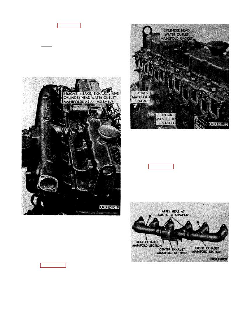
FIGURE 173. EXHAUST MANIFOLD ASSEMBLY SHOWING HEAT APPLICATION POINTS FOR SEPARATION OF SECTIONS |
|
||
| ||||||||||
|
|
 (6) Refer to figure 171 and remove intake.
exhaust and cylinder head water outlet
manifolds as a unit.
Note. The intake and exhaust manifolds
may be separated after they have been
removed from the cylinder head studs.
INTAKE , EXHAUST, AND CYLINDER
HEAD WATER OUTLET MANIFOLD
GASKETS.
(8) Figure 173. (A) Apply heat to joint of
front exhaust manifold section and sep-
arate the front section from the center
section. (B) Remove the rear exhaust
manifold section from the center section
in the same manner.
INTAKE, EXHAUST, AND CYLINDER
HEAD WATER OUTLET MANIFOLDS
AT CYLINDER HEAD ASSEMBLIES -
TOP VIEW.
(7) Figure 172. (A) Remove and discard
six cylinder head water outlet manifold
gaskets. (B) Remove and discard six
intake manifold gaskets. (C) Remove
BLY SHOWING HEAT APPLICATION
and discard six exhaust manifold gas-
POINTS FOR SEPARATION OF
kets.
SECTIONS.
119
|
|
Privacy Statement - Press Release - Copyright Information. - Contact Us |
