 |
|||
|
|
|||
|
Page Title:
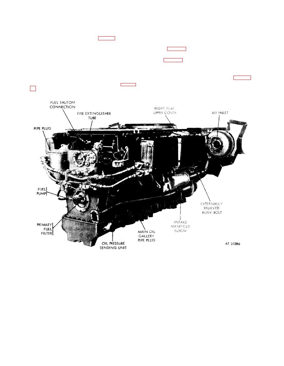
Figure 8-1. Engine connection points--right front view. |
|
||
| ||||||||||
|
|
 1 cylinder on both banks, when oil flows tighten
(22) Piston oiler nozzle pressure should be
readable.
bolts.
Note. Pressure will not reach the desired
(17) Install starter cables (fig. 1-2).
o p e r a t i n g level until the engine speed has been
(18) Wash all fuel and oil from engine.
( 1 9 ) Check all thermocouple connections. If
increased (para 8-1i. (2)).
connected
correctly, should
read
ambient
(23) Exhaust manifold temperatures should
register (para 8-1f).
temperature; if connected incorrectly, scale
r e a d i n g will go to top of scale.
( 2 4 ) Visually inspect engine for fuel and oil
leaks.
(20) Start engine at IDLE speed (para c,
below).
( 2 5 ) Ready for engine test schedule (table 8-
1).
( 2 1 ) Check engine main oil pressure (para 8-
8-4
|
|
Privacy Statement - Press Release - Copyright Information. - Contact Us |