 |
|||
|
|
|||
|
Page Title:
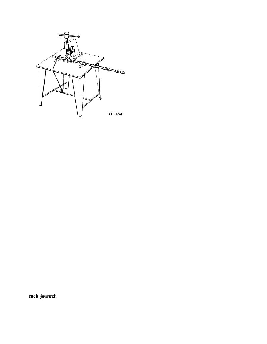
Figure 6-214. Improvised camshaft trueing device. |
|
||
| ||||||||||
|
|
 (5) Check
runout
of
each
camshaft
bearing
journal.
Support
the
camshaft
in
"V"
blocks at the adjacent journals, and using a dial
indicator,
check
and
record
journal
runout
(TIR) dimensions. If runout exceeds 0.002 inch,
cam
shaft
must
be
straightened.
(b) S t r a i g h t e n i n g c a m s h a f t .
(1) Install camshaft on trueing device
with
bearing journal having the maximum
runout
(TIR)
positioned
under
the
pressing
spindle. (The camshaft journals must be resting
on the support blocks when rotating the cam-
shaft to determine the runout.) Set dial on in-
dicator
to
"zero"
and rotate camshaft to
determine location of runout (TIR) and record
reading.
(2) Turn camshaft until bearing
journal
marked to indicate the maximum runout
(high side) is adjacent to the spindle (do not
press on journals). Apply spindle pressure on the
trueing device.
camshaft
until
dial
indicator
reads
ap-
(a) C h e c k i n g c a m s h a f t b e a r i n g j o u r n a l
proximately one
half
of
the
TIR
reading
run-out. Camshafts may be straightened if the
recorded
in
(a),
above.
Release
pressure
on
runout
of
any
one
camshaft
bearing
surface
cam shaft and recheck runout by turning
(journal), when using a dial indicator, does not
camshaft several revolutions.
exceed 0.060 inch total indicator reading (TIR)
Note. Pressing force required to straighten
when
supported
at
the
two
adjacent
bearing
cam shaft is a matter of judgement. It may be
journals. Camshafts that exceed 0.060 inch
necessary to turn camshaft and apply pressing
runout between any two journals must be
force several times in order to acquire the
discarded.
Maximum
journal
runout
of
technique necessary to true the bearing journal.
straightened camshafts is 0.002 inch (TIR)
(3) Apply pressure as required until the
when supported at the two adjacent journals.
journal is within the 0.002 maximum TIR.
After
straightening
a
camshaft,
the
maximum
(4) R e p o s i t i o n c a m s h a f t o n s u p p o r t s
acceptable runout of the center bearing journal,
and
true other bearing journals is a similar
when supported at the end journals, is 0.015
manner.
inch (TIR). Check
camshaft
bearing
journal
(5) After trueing all bearing journals,
runout as follows:
recheck camshaft as outlined in procedure (a),
(1) Support the camshaft at the two
above.
If
readings
do
not
meet
dimensions
end journals in "V" blocks on a surface plate or
specified,
repeat
trueing
operation.
other available centering device, such as a
(c) Inspection
of
camshaft
after
machine
lathe.
straightening.
(2) Position
a
dial
indicator
at
the
(1) M a g n a f l u x
each
camshaft
and
center bearing journal and obtain a zero reading
inspect for cracks. Observe transition areas at
on the dial.
bearing surfaces and at cam lobe bases. Cam-
(3) Rotate the camshaft and determine
shafts with evidence of cracks must be discarded.
the maximum travel of the dial indicator needle.
(2) Inspect for damage to bearing
If travel (TIR) exceeds 0.015 inch the camshaft
journals. M i n o r n i c k s a n d s c r a t c h e s c a n b e
must
be
straightened.
removed using crocus cloth.
(4) Repeat steps (2) a n d (3), a b o v e f o r
(3) Check bearing journals for out-of-
each
bearing journal and mark position and
round to be certain area was not flattened during
dimension of maximum dial indicator reading at
trueing.
Maximum
acceptable
out-of-round
is
0.002
inch
(TIR).
Replace
camshaft
if
this
tolerance
is
exceeded.
6-179
|
|
Privacy Statement - Press Release - Copyright Information. - Contact Us |