 |
|||
|
|
|||
|
Page Title:
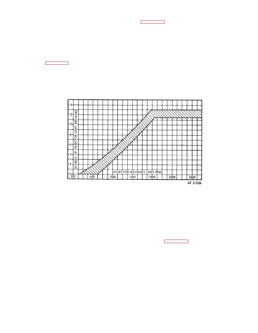
Figure 6-200. Fuel injector advance unit curve |
|
||
| ||||||||||
|
|
 (0), figure 6-199b, to reduce speed and counter
counter reading at each 200 rprn increment
switch, motor switch, and master switch handle
increase, beginning at 600 rpm and continue
to the "OFF" position.
through
to
2600
rpm.
Note. Injector pump advance assembly
(m) Reduce speed to 600 rpm and re-
will be hot following test. Operator should wear
check counter reading. If this reading does not
gloves when removing unit from test stand.
check with the original repeat the test. Check the
readings taken at each 200 rpm increase against
(o) Loosen fasteners and remove cover.
Remove
bearing
caps
and
remove
unit
from
similar points on the approved advance unit
bench. Remove oil transfer shaft. Place injector
curve, figure 6-200. If the recorded advance
advance pump assembly on oil drain tray with
readings fall within the prescribed limits on the
small gear end up. Place advance assembly in a
curve,
the
test
is
complete.
If
the
advance
readings do not meet the curve limits, proceed
clean
dirt-free
container,
preferably
a
with step (p) below.
polyethylene bag, for storage after draining and
cooling.
(n) Turn speed regulator control to zero
Figure
6-200.
Fuel
injector
advance
unit
curve.
(p) Repeats steps (h) through (m) to
(r) Push speed control stop switch to
check
previous readings. If advance assembly
disengage eddy current clutch. Turn counter,
fails to pass the test, it must be adjusted. Note
motor, and motor starter off.
whether advance assembly advances too soon or
(s) Loosen fasteners and remove cover.
too
late.
Either
condition
can
normally
be
Remove two cotter pins, and loosen the two
corrected
by
rotating
the
advance
flyweight
slotted nuts enough to permit adjusting ring
adjusting ring.
rotation. See figure 6-201.
Note. The advance assembly should be
Note. Do not turn the adjusting ring more
retarded slightly if the advance varies more than
than 1 /
16
of
an
inch
during
any
one
ad-
2 degrees at 300 rpm when the oil pressure drain
justment.
button is depressed. This variance indicates the
mechanical retard stop is not in phase with the
hydraulic valve.
6-168
|
|
Privacy Statement - Press Release - Copyright Information. - Contact Us |