 |
|||
|
|
|||
|
Page Title:
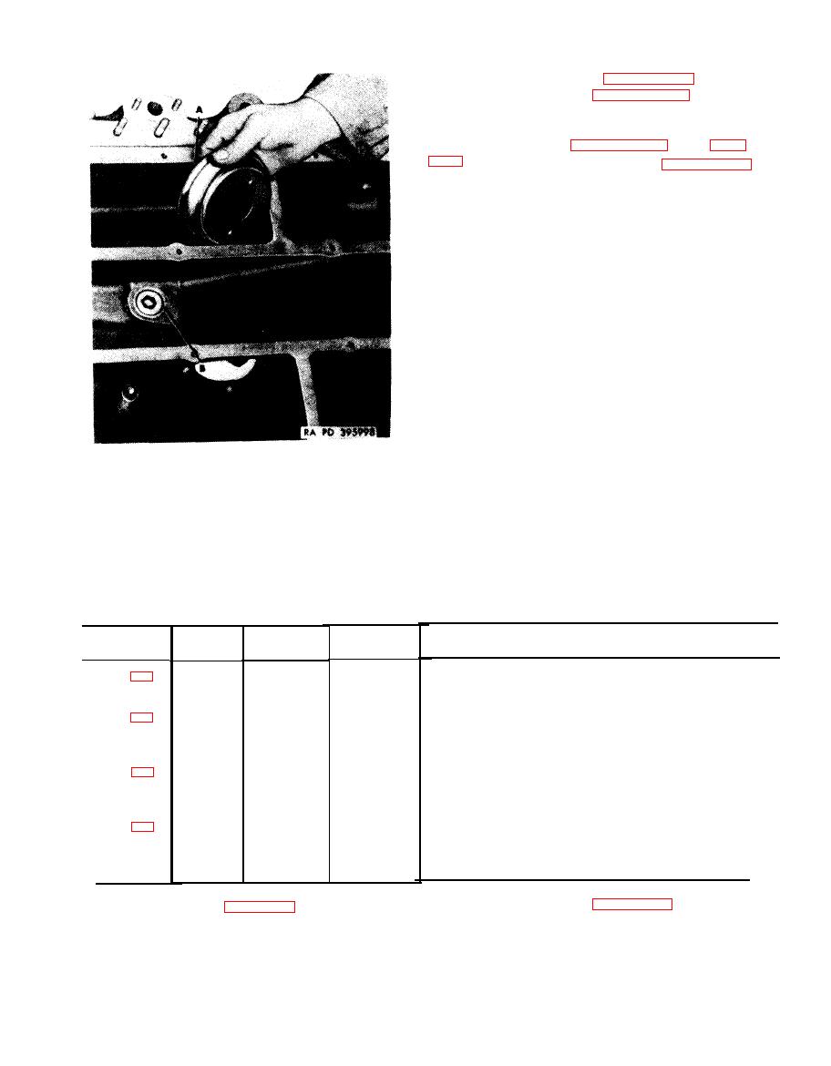
Figure 6-97. Removing or installing pressure oil pickup cover. |
|
||
| ||||||||||
|
|
 pan gasket flange must not be out-of flat by more
than 0.004-inch per foot.
4 C for general welding instructions and (1) and
(2), below, for specific information on welding
repair of the oil pan.
(1) Oil pan bottom surfaces. T h e w e l d i n g
repair of chips, cracks, and the replacement of
m e t a l is permissible in the oil pan to prevent oil
leakage between compartments or from cast
passages. Repair cracks that do not extend over
12 inches lengthwise and when there are not
m o r e than three cracks running crosswise within
a six inch area.
(2) Oil pan baffles. Sections of missing
metal in oil baffles may be replaced, but care
must be exercised when replacing baffles im-
mediately adjacent to and attaching to the oil
pan outer walls at the engine mounting bosses.
M o u n t bosses may also be repaired if chipped or
c r a c k e d . After welding repair of the oil pan, leak
Remove
test compartments and cast passages. Pressure
1. Remove pressure oil pickup cover (A).
test is not necessary.
2. Remove oil pan pipe plug (B).
Install
1. Install oil pan pipe plug (B).
2. Install pressure oil pickup cover (A).
oil pickup cover.
Table 6-21. Oil Pan Standard and Oversize Stud Identification
Stud size
No.
Fig.
Set ting
Ref
and length
height
No.
req'd
No.
5/16-18(3/4)
x5/
16(23/32)
x
3-9/32
(STD)
2
2-13 / 16
21
(0.003 in. OS)
(0.007 in. OS)
1-21 / 32
5/16-18(15/16) x5/ 16-24(25/32) x 2-1/8 (STD)
2
24
(0.003 in. OS)
(0.007 in. OS)
(0.012in. OS)
5/ 16-18(3/4) x5/ 16-24(19/32) x 1-7/16 (STD)
8
25 / 32
17
(0.003 in. OS)
(0.007 in. OS)
(0.012 in. OS)
3/8-16(15/16)
x3/
8-24(13/16)
x
2-3/32
(STD)
56
1-11 / 32
14
(0.003 in. OS)
(0.007 in. OS)
88.
identification.
6-96
|
|
Privacy Statement - Press Release - Copyright Information. - Contact Us |