 |
|||
|
|
|||
|
|
|||
| ||||||||||
|
|
 6-29. Disassembly
a. Cylinder. Disassemble cylinder assembly
following instructions which accompany figures
N o t e . The 12 rocker arm cover assemblies are
machined with cylinder assemblies as matched
units. The covers are stamped with matching
numbers (fig. 5-105) to correspond with the
number stamped on the cylinder. Keep covers
with their respective cylinders.
W a r n i n g : The valves and locks are under
heavy spring tension. Exercise extreme care
when removing locks, retainers and springs.
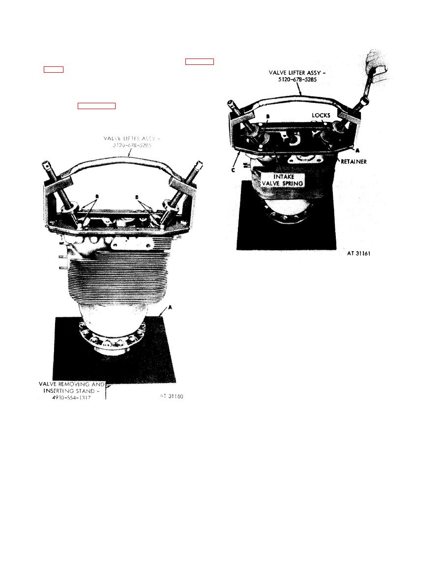
1. Compress exhaust valve spring and upper retainer.
2. Remove two valve locks (A) from the groove in valve
stem. Tap valve spring retainers to free locks. Carefully
loosen lifter screw to release valve springs.
3. Remove intake valve spring upper retainer locks (B)
in the same manner.
4. Remove lifter assembly (C).
Figure 6-48. Compressing exhaust valve
springs to remove or install upper valve
spring retainer and locks.
1. Place cylinder with valves, springs, and retainers on
removing and inserting valve stand - 4910-554-1317
(A).
2. Secure valve lifter assembly - 5120-678-5285 to the
cylinder head with four bolts (B) and flat washers.
valve lifter assembly - 5120-678-5285 and
removing and inserting valve stand -
4910-554-1317.
6-52
|
|
Privacy Statement - Press Release - Copyright Information. - Contact Us |
