 |
|||
|
|
|||
|
Page Title:
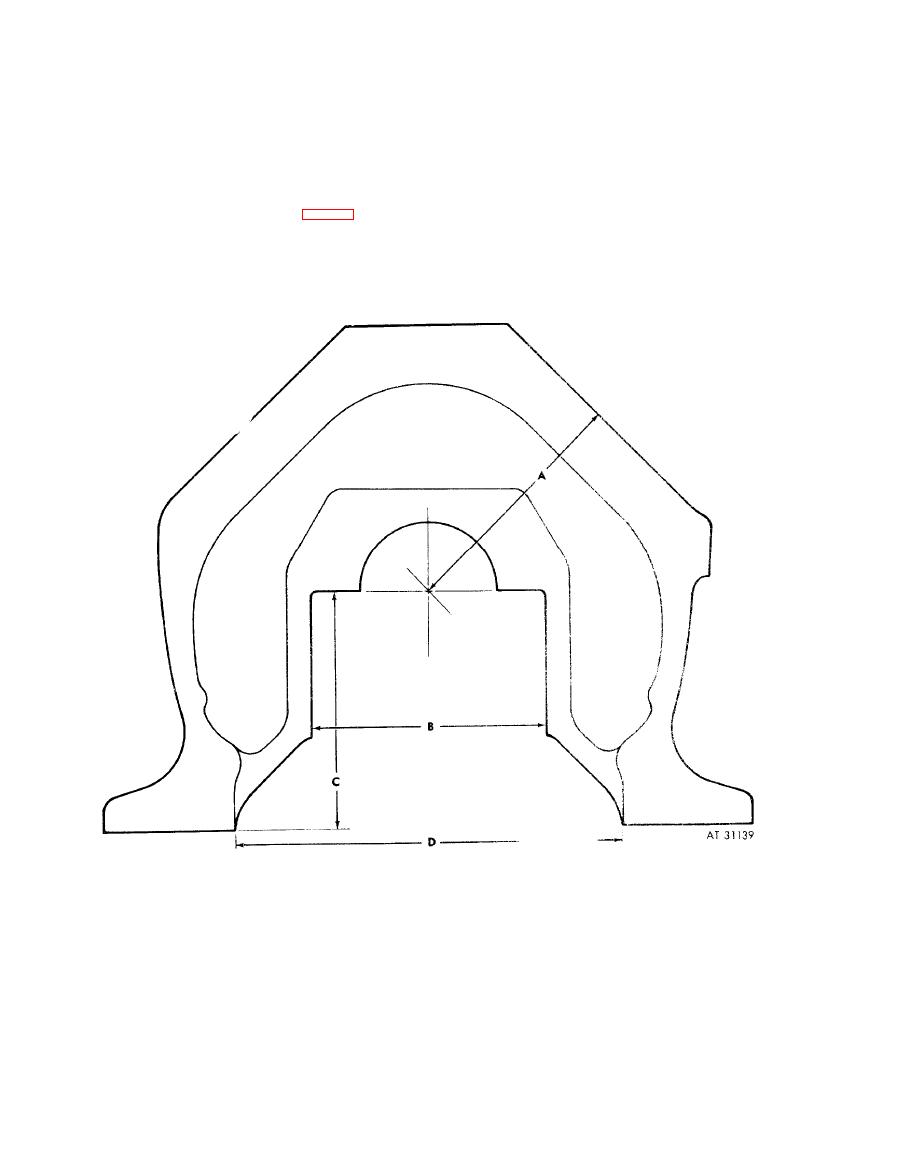
Figure 6-14. Points of measurement for checking crankcase. |
|
||
| ||||||||||
|
|
 (2) To detect dimensional changes caused by
(d)
From
cylinder
mounting
deck
to
welding repair, precisely measure crankcase at
crankshaft bearing support bore centerline using
several key positions depending upon the
a suitable plug or bore in the crankcase bearing
location of the repair. For repair to side walls,
bore (A). This measurement shall be within
measure
the
positions
outlined
in
steps
(a)
8 . 3 7 7 - 8 . 3 6 9 inch.
through
(d).
(e) Oil pan rail shall be flat within 0.010-
inch when all four corners are on the same plane.
(a) Across the main bearing cap support
web machined surfaces (B, fig. 6-14).
(3) For repair in other locations, measure in
(b) Across the inside of the crankcase at
the appropriate locations to insure that critical
the junction of the side wall and the oil pan rail
dimensions
are
held.
Record
dimensions
for
(D).
future use.
(c) From oil pan rail face to main bearing
cap support face (C).
Figure 6-14. Points of measurement for checking crankcase.
6-20
|
|
Privacy Statement - Press Release - Copyright Information. - Contact Us |