 |
|||
|
|
|||
|
Page Title:
Shrouds, Cylinder Deflectors and Nozzle and Holder Assemblies |
|
||
| ||||||||||
|
|
 Note. Removal or installation of shrouds and
cylinder deflectors is the same for both left and
Nozzle and Holder Assemblies
r i g h t banks of the engine. For instructional
Refer to Table 5-7 for illustrations and
purposes, the right bank shrouds and cylinder
disassembly instructions. Figure references are
deflectors are shown.
listed in the table.
Table 5-7. Shrouds, Cylinder Deflectors, and Nozzle
Holder Assemblies
Component
Figure Reference
Sh roud Pl ates and Cylinder Deflectors
Nozzle and Holder Assemblies
Disconnect
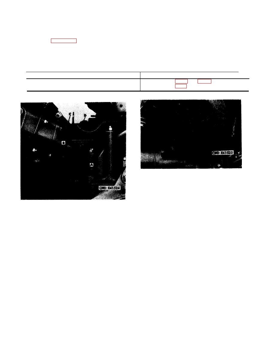
1. Remove four plate nuts (A) from lower right rear
engine shroud.
2. Remove machine screw (B) from shroud.
Connect
1. Install machine screw (B) in lower right rear engine
shroud.
2. Install four plate nuts (A) on shroud.
Remove
1. Remove two machine screws (A) attaching lower right
camshaft drive shroud.
Figure 5-98. Disconnecting or connecting
2. Remove lower shroud (B).
lower right engine shroud-top view.
3. Remove machine screw (C) attaching upper right
camshaft drive shroud.
4. Remove upper shroud (D).
Install
1. Position upper right camshaft drive shroud (D) on
engine.
2. Install machine screw (C) securing upper shroud.
3. Position lower right camshaft drive shroud (B) on
ermine.
4. Install two machine screws (A) securing lower shroud.
camshaft drive shrouds-right side.
5-58
|
|
Privacy Statement - Press Release - Copyright Information. - Contact Us |