 |
|||
|
|
|||
|
Page Title:
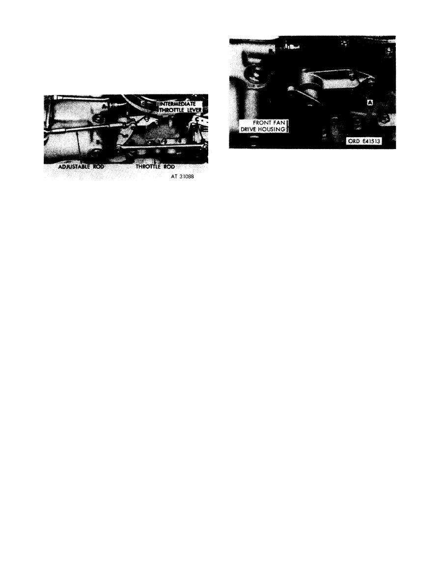
Figure 5-82. Disconnecting or connecting throttle rods at intermediate throttle lever. |
|
||
| ||||||||||
|
|
 Remove
1. Remove three self-locking nuts (A) attaching in-
termediate throttle lever support to front fan drive
housing.
Disconnect
2. Remove lever support (B), shaft, and throttle lever as
1. Remove cotter pin, slotted nut (A), and bolt attaching
a unit.
throttle adjustable rod. Remove adjustable rod.
Install
2. Remove cotter pin, slotted nut (B), and bolt attaching
1. Position lever support (B), shaft, and throttle lever as
throttle rod to intermediate throttle lever.
a unit on front fan drive housing.
3. Remove cotter pin, slotted nut (C), flat washer, and
2. Install three self-locking nuts (A) securing lever
bolt attaching throttle rod to injection pump lever.
support to drive housing.
Remove red.
Connect
1. Position throttle rod on injection pump lever. Install
bolt, flat washer, slotted nut (C), and cotter pin
intermediate throttle lever support.
securing rod.
2. Install bolt, slotted nut (B), and cotter pin securing
throttle rod to intermediate throttle lever.
3. Position throttle adjustable rod on intermediate
throttle lever. Install bolt, slotted nut (A), and cotter
pin securing rod.
throttle rods at intermediate throttle lever.
5-50
|
|
Privacy Statement - Press Release - Copyright Information. - Contact Us |