 |
|||
|
|
|||
|
Page Title:
Figure 5-51. Removing or installing cylinder head plates -right side. |
|
||
| ||||||||||
|
|
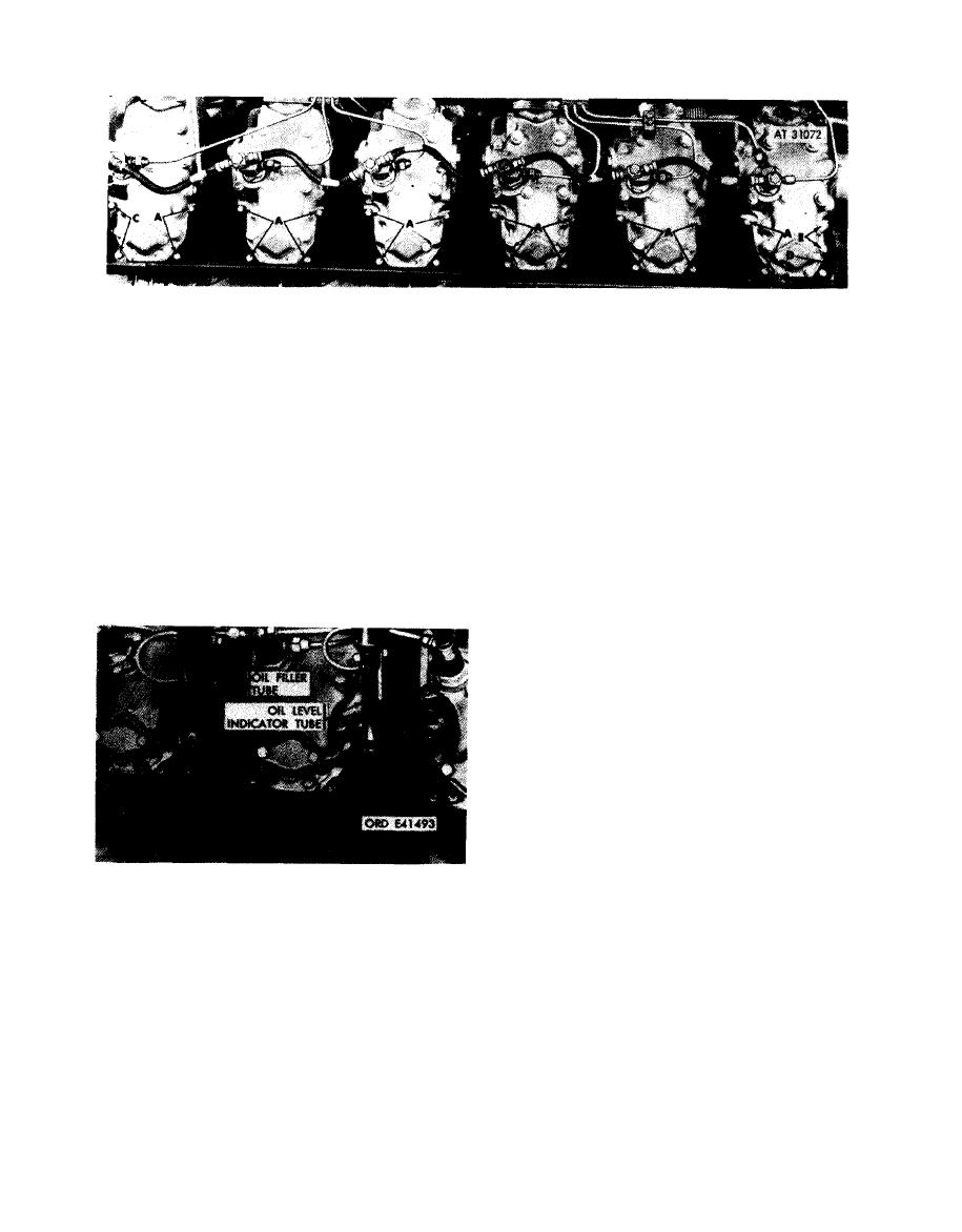 Remove
Note. The cylinder head plates on the left side
1. Remove 20 hex head screws(A) and lock washers and
of the engine are removed or installed in the
remove five cylinder head plates.
same manner, except for the plates surrounding
2. Remove plate nut (B) from front cylinder head end
the oil filler and oil level indicator tubes (be-
plate.
t w e e n cylinders lL, 2L, and 3L).
3. Remove two hex head screws (C) and lock washers
and remove front end plate.
Install
4. Remove plate nut (D) from rear cylinder head end
1. Position rear cylinder head end plate and install two
plate.
hex head screws (E) and lock washers securing plate.
5. Remove two hex head screws (E) and lock washers
2. Install plate nut (D) on end plate.
and remove rear end plate.
3. Position front cylinder head end plate and install two
hex head screws (C) and lock washers securing plate.
4. Install plate nut (B) on end plate.
5. Position five cylinder head plates and install 20 hex
head screws (A) and lock washers securing plates.
plates -right side.
Remove
Note. The oil filler and oil level indicator tubes
m u s t be removed before cylinder head plates
between cylinder Nos. 1 L , 2L, and 3L can be
removed.
1. Remove two machine screws (A) and lock washers
and remove oil filler tube plate.
2. Remove two machine screws (B) and lock washers
and remove oil level indicator tube plate.
Install
1. Position oil level indicator tube plate and install two
machine screws (B) and lock washers securing plate.
2. Position oil filler tube plate and install two machine
Figure 5-52. Removing or installing oil filler
screws (A) and lock washers securing plate.
and oil level indicator tube plates -
engines with one piece oil filler tube.
5-28
|
|
Privacy Statement - Press Release - Copyright Information. - Contact Us |
