 |
|||
|
|
|||
|
Page Title:
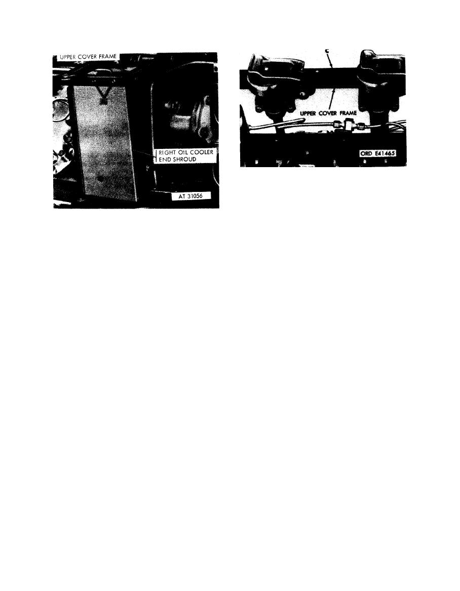
Figure 5-17. Disconnecting or connecting upper cover frame-right rear view. |
|
||
| ||||||||||
|
|
 Remove
1. Remove two self-locking nuts and bolts (A) attaching
oil indicator tube retaining strap and remove strap.
Note. Some early engines used weld nuts in
lieu o f s e l f - l o c k i n g n u t s
Disconnect
<
1. Remove two machine screws (A) attaching upper
cover frame to right oil cooler end shroud.
2. Remove two self-locking nuts and bolts (B) attaching
2. Remove two bolts (B) attaching frame to right rear
oil filler tube retaining strap and remove strap.
shroud.
3. Remove left upper cover frame (C).
3. Remove right upper cover frame.
Install
Connect
1. Position right upper cover frame (C) on right side of
that h a v e
been
Note. On
installations
engine.
m o d i f i e d , oil filler tube will be relocated b e h i n d
2. Install two bolts (B) securing frame to right rear
turbosupercharger and retaining straps will be
shroud.
discarded.
3. Install two machine screws (A) securing upper cover
frame to right oil cooler. end shroud.
1. Position left upper cover frame (C) on left side of
engine.
2. Position oil filler tube retaining strap around oil filler
upper cover fra me-right rear view.
tube and install two self-locking nuts and bolts (B)
securing strap.
3. Position oil indicator tube retaining strap around oil
indicator tube and install two self-locking nuts and bolts
(A) securing strap.
Figure 5-18. Removing or installing oil
indicator and oil filler tube to upper frame
retaining strap-left side engines without
relocated oil filler tube.
5-10
|
|
Privacy Statement - Press Release - Copyright Information. - Contact Us |