 |
|||
|
|
|||
|
Page Title:
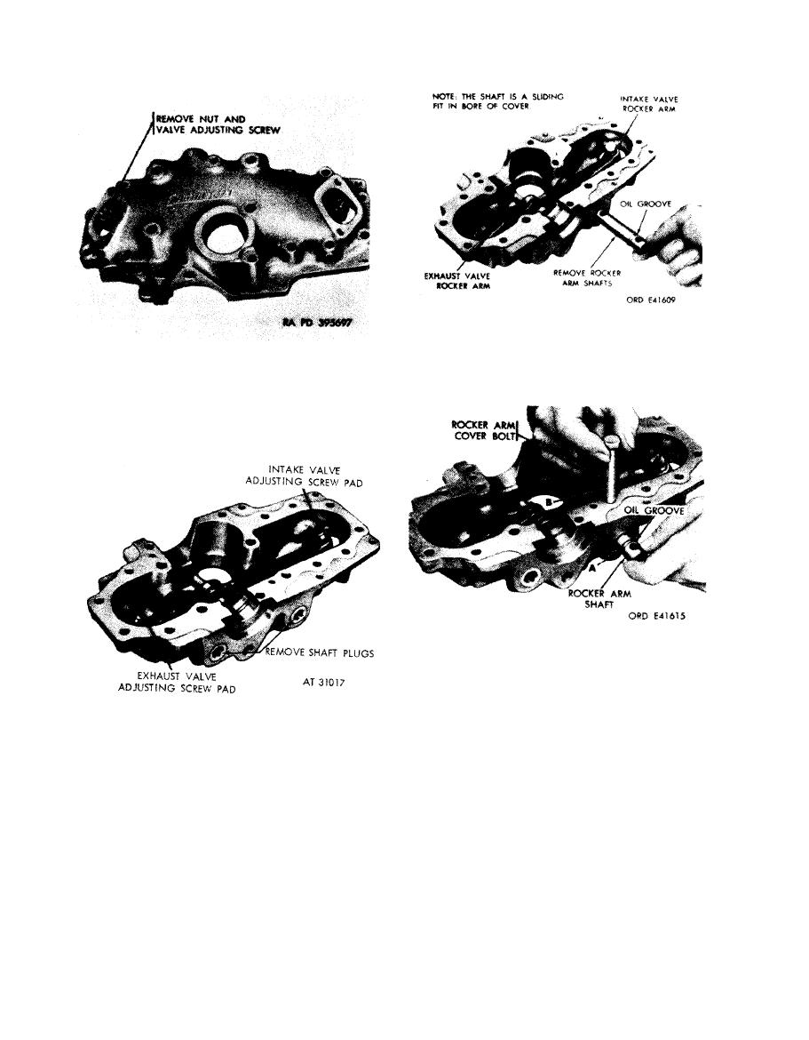
Figure 4-158. Removing or installing valve adjusting screw. |
|
||
| ||||||||||
|
|
 shafts and valve rocker arms.
Note. Valve rockers do not have to be removed
to replace adjusting screws.
adjusting screw.
1. Position valve rocker arms in reeker arm cover. Insert
valve rocker arm shaft ( A ) through bore in rocker arm
cover and rocker arm.
2. Use one rocker arm cover bolt (B) to a line hole in
shaft with bolt hole in cover. Push shaft into position,
without twisting, to retain alinement.
Figure 4-159. Removing or installing valve
Note. Under normal circumstances, if rocker
rocker arm shaft plugs.
arm cover is damaged, the entire cylinder and
cover must be replaced. In cases of emergency.
the rocker arm covers can be changed hut it will
require special attention to insure alinement of
the two halves of the camshaft base.
and valve rocker arm shafts.
4-78
|
|
Privacy Statement - Press Release - Copyright Information. - Contact Us |