 |
|||
|
|
|||
|
Page Title:
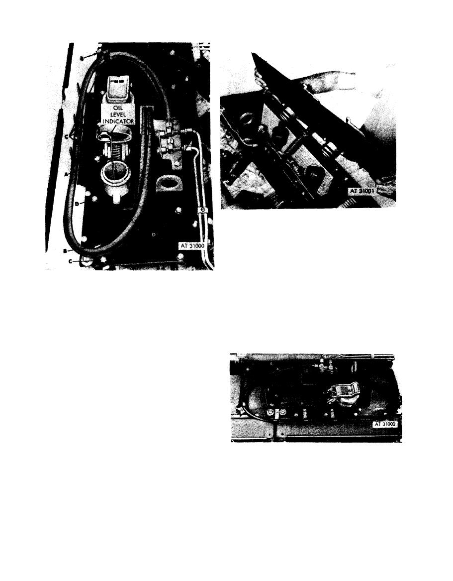
Figure 4-135. Removing or installing oil level indicator and oil filter tube upper cover-with splash pan installation. |
|
||
| ||||||||||
|
|
 Remove
1. Raise cover plate (A) until oil drain hose clamp (B) is
accessable.
2. Loosen hose clamp (B) and disconnect oil drain hose
from cover plate.
3. Remove cover plate (A) and remove and discard four
preformed packings (C).
Install
Remove
1. Install four new preformed packings (C) and position
1. Lift cover and remove oil level indicator (A).
cover plate (A) on frame.
2. Remove drain hose (B) from retaining brackets.
2. With cover plate partially raised, connect oil drain
3. Remove seven cap screws (C) attaching valve and
hose to cover plate and tighten hose clamp (B).
hose brackets to shroud plate.
3. Position cover plate (A) on frame.
4. Remove five cap screws (D) attaching plate to frame.
Install
indicator and oil filter tube upper
1. Install five cap screws (D) securing plate to frame.
cover-with splash pan installation.
2. Install seven cap screws (C) securing valve and hose
brackets to shroud plate.
3. Install drain hose (B) on retaining brackets.
4. Install oil level indicator (A) I and close cover.
indicator and oil filler and oil level
indicator
tube
shroud
plate
bolts-tubes
with splash pan installation.
cover
p l a t e -relocated
oil
filler
tube
modified
installed
view.
4-66
|
|
Privacy Statement - Press Release - Copyright Information. - Contact Us |