 |
|||
|
|
|||
|
Page Title:
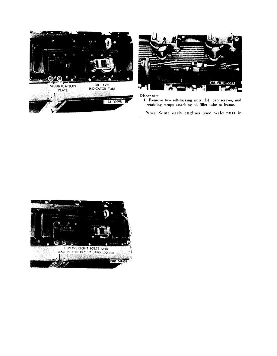
Figure 4-130. Removing or installing left front upper cover-modified upper-cover installation |
|
||
| ||||||||||
|
|
 Remove
lieu of self-locking nuts,
1. Remove six bolts (A) and remove oil level indicator
tube shroud plate.
2. Remove two self-locking nuts (A), cap screws, and
2. Remove three bolts (B) attaching modification cover
retaining straps attaching oil level indicator tube to
plate and upper cover to frame.
frame.
Connect
Note. Do not remove remaining three bolts
attaching
modification
cover
plate
to
upper
cover.
Note. On installations that have been
Maintain upper cover as an assembly.
modified, oil filler tube will be relocated behind
Install
turbosupercharger and retaining straps will be
1. Install three bolts (B) securing modification cover
discarded.
plate and upper cover to frame.
2. Position oil level indicator tube shroud plate and
1. Position retaining straps
and install two self-locking
install six bolts (A).
nuts (A) and cap screws,
securing straps and oil level
Figure 4-129. Removing or installing oil
indicator tube to frame.
level
indicator
tube
shroud
plate-modified
2. Position retaining straps
and install two self-locking
shroud plate installation.
nuts (B) and cap screws
securing straps and oil level
indicator tube to frame.
Figure
4-131.
Disconnecting
or
connecting
oil filler and oil level indicator tube
retaining straps-one piece type oil filler and
indicator tubes installation shown.
front
upper cover-modified
upper-
cover installation.
4-64
|
|
Privacy Statement - Press Release - Copyright Information. - Contact Us |