 |
|||
|
|
|||
|
Page Title:
Figure 4-98 Removing or installing fuel/water separator filter cover. |
|
||
| ||||||||||
|
|
 Remove
1. Remove cover (A).
2. Remove and discard preformed packing (B).
Install
Note. Replacement coalescer elements
and
preformed packing are available in parts kit -
2910-801-1152. Purge fuel system, refer to
Remove
pertinent
operator's
manual.
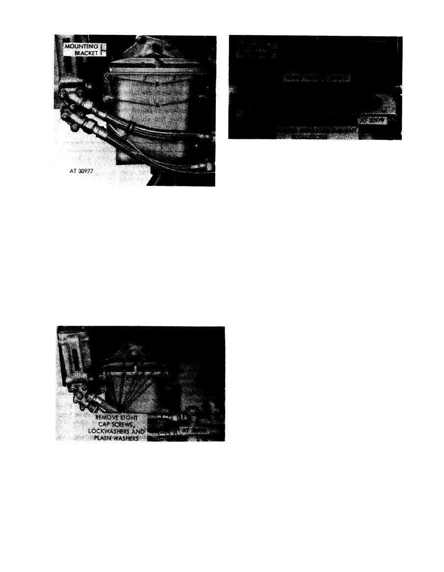
1. Remove lower two cap screws (A), lock washers, and
plain washers.
1. Install new preformed packing (B).
2. Remove upper two cap screws (B) and lock washers
2. Install cover (A).
and remove filter assembly from bracket.
Note. Fuel inlet, outlet, and drain elbows are
fuel / water separator filter cover.
not part of the filter assembly and must be in-
stalled in the replacement filter.
Install
1. Position filter assembly on bracket and install upper
two cap screws (B) and lock washers.
2. Install lower two cap screws (A), lock washers, and
plain washers.
Figure
4-96.
Removing
or
installing
fuel / water separator filter assembly.
Note. Entire
area
around
the
fuel
/
water
separator filter should be thoroughly cleaned to
prevent the entry of dirt or other foreign objects
before removing the cover.
Figure 4-97. Removing
or
installing
fuel / water separator filter cover bolts.
4-49
|
|
Privacy Statement - Press Release - Copyright Information. - Contact Us |