 |
|||
|
|
|||
|
Page Title:
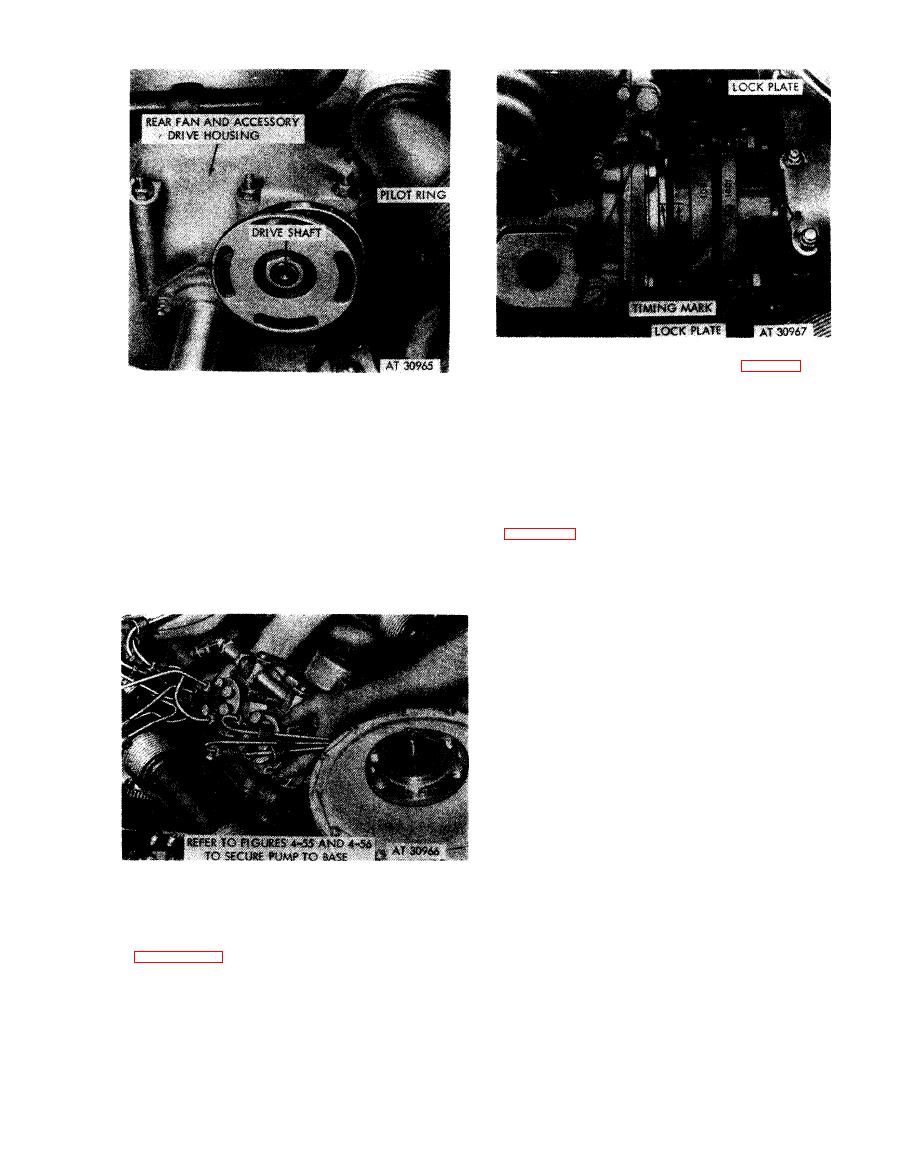
Figure 4-77. Installing fuel injection pump assembly on engine. |
|
||
| ||||||||||
|
|
 installed in coupler sleeve.
1 . Postion fuel injection pump coupler sleeves (A)
making sure timing marks on bearing retaining plate
Note.
The fuel injection pump diaphragm
and coupler hub remain alined as shown. These marks
coupler parts are not matched sets, and parts are
m u s t be alined before attempting to assemble the
interchangeable between assemblies. The
coupler.
coupler hub and pilot ring on the drive shaft
2. Loosely position four lock plates, lock washers, and
need not be removed or replaced unless they are
bolts (B) in drive shaft coupler sleeves. These bolts will
not be tightened until gear backlash has been removed,
damaged. Check torque tightness of nut securing
with timing marks on pump alined as instructed in
coupler to drive shaft (900 lb-in.).
Figure 4-76. Fuel injection pump diaphragm
coupling and pilot ring on hub before pump
coupler sleeve s-splined coupler.
installation.
Note. Be sure lower right fuel injection pump
mounting bolt is inserted in injection pump
before pump is seated on mounting base. It
cannot be installed with pump in position. Refer
to figures 4-55 and 4-56 to secure pump to base.
assembly on engine.
4-39
|
|
Privacy Statement - Press Release - Copyright Information. - Contact Us |