 |
|||
|
|
|||
|
|
|||
| ||||||||||
|
|
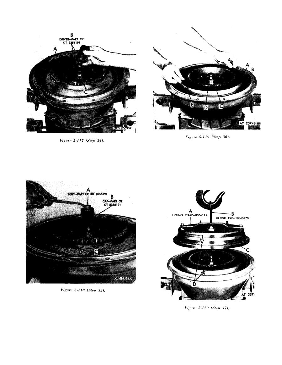 Install lockup clutch back plate (A), seal ring (B),
Install turbine assembly (A). Install coned part of
hook-type seal ring (C), and lockup clutch plate
snap ring driver (B) on end of turbine shaft. Install
(D).
snap ring (C) on driver. Install knurled cap of snap
NOTE
ring driver (B). (Driver is part of kit--5120-572-
Aline balance marks (E) on converter
8663 (8356191)).
pump and back plate.
Install bolt (A), and tighten it against cap (B) until
snap ring (C) snaps into groove (D). Remove driver
kit parts. (Bolt and cap are part of kit--5 120-572-
Using lifting strap 4910-572-8608 (8356175) (A)
8663 (8356191)).
a n d lifting eye 4910-673-8301 (10865773) (B),
install pump cover assembly (C). Do not remove
strap (A) and eye (B) at this time.
NOTE
Aline balance marks (D).
|
|
Privacy Statement - Press Release - Copyright Information. - Contact Us |
