 |
|||
|
|
|||
|
|
|||
| ||||||||||
|
|
 TM 9-2520-249-34&P
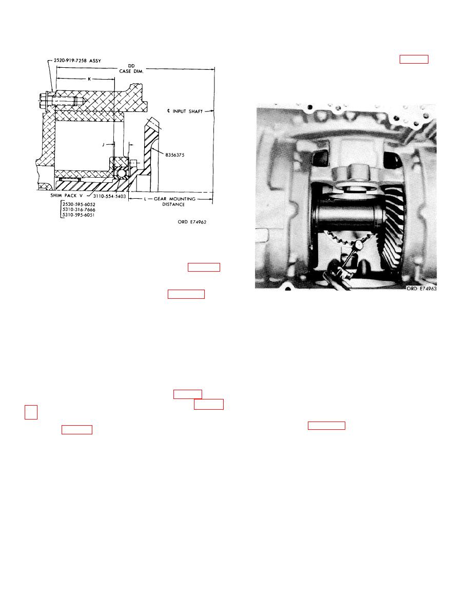
etched on the gear. Backlash may be adjusted by
adding or removing shims from shim pack V fig. 8-8).
NOTE
The cross shaft must be held stationary to
obtain correct backlash reading.
Figure 8-8. Nominal shims for brake coolant pump gear
From the bottom of the bearing bore in the pump cody,
to upper surface of the pump cover (pump assembled).
substituting dimensions for DD, J, K and L in the formula
Figure 8-9. Checking coolant pump drive gear tooth
V = DD - K - J - L.
contact pattern and backlash
NOTE
DD is stamped on a web of the bevel gear
g. When gear pattern, backlash, and bearing
housing; J was obtained in a, above; K was
preload are properly established for all the gears,
obtained in b, above; L is the gear mounting
recheck all bolts for tightness.
distance (MD) etched on the pump drive gear.
8-10. Preliminary Assembly
d. Select the combination of shims 2530-595-
All thrust surfaces, gears, sealrings, splines, bushings
6052, 5310-316-7666 and 5310-595-6051 which most
and bearings must be oiled as they are installed.
nearly equal V. Install the shims and gear (fig. 8-8).
8-11. Assembly Pictorial Steps
The assembly of the transmission from subassemblies
f.
Check the gear tooth contact pattern and
(as discussed in chapter 7) is outlined in the following
backlash (fig. 8-9). The backlash (BL) should be that
consecutive pictorial steps (1 through 125).
8-5
|
|
Privacy Statement - Press Release - Copyright Information. - Contact Us |