 |
|||
|
|
|||
|
Page Title:
CHAPTER 7. REPAIR OF SUBASSEMBLIES |
|
||
| ||||||||||
|
|
 TM 9-2520-249-34& P
CHAPTER 7
REPAIR OF SUBASSEMBLIES
Section I. CONVERTER PUMP COVER AND LOCKUP CLUTCH ASSEMBLY-REPAIR
7-1.
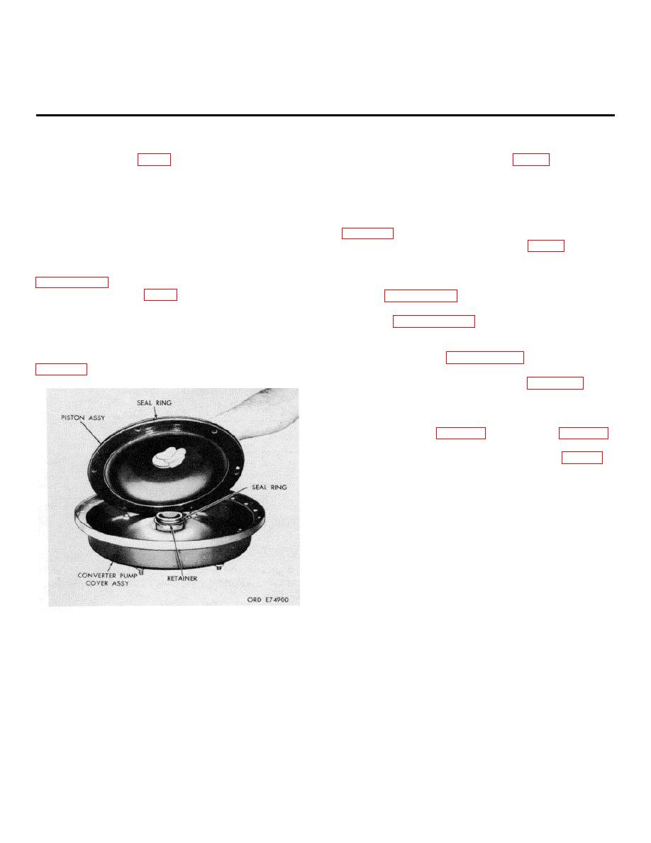
clutch piston assembly (11). Lay the sealring flat after
Converter pump cover assembly (5) is a pressed steel
removal so it will not stretch.
assembly with six drive studs at the front to attach it to
d. Remove preformed packing (9) from the
the engine flex-drive plates. The rear ends of these six
hub of pump cover assembly (5). Also remove seal
studs enter blind holes in lockup clutch piston assembly
retainer (8), if loose, or for replacement. Refer to
(11), causing the cover and piston to rotate as a unit. A
center hub enters the end of the engine crankshaft for
alinement. Lockup clutch oil pressure, applied between
piston and cover, moves the piston against lockup
replacement. For removal collapse the bushing and lift
clutch disk (13) for clutch application.
Refer to
it out.
7-3.
Cleaning
7-2.
Refer to paragraph 5-2 for cleaning recommendations.
a. Compress the center part of lockup clutch
7-4.
Inspection and Repair
piston assembly (11) by hand and remove retaining ring
Refer to paragraph 5-3 for inspection and repair
(12) with snapring pliers.
recommendations.
b. Remove lockup clutch piston assembly (11)
7-5.
Repair Standards
from converter pump cover assembly (5). Refer to
repair standards.
7-6.
Assembly (FO -3)
a. If bearing (7) was removed from converter
pump cover assembly (5), press in a new bearing.
Using handle (12, table 3-1)and driver (9, table 3-1),
install the bearing 1.00 to 1.04 inches below the outer
bolt ring surface inside of the cover assembly (fig. 7-2).
Figure 7-1. Removing (or installing lockup clutch piston
assembly.
7-1
|
|
Privacy Statement - Press Release - Copyright Information. - Contact Us |