 |
|||
|
|
|||
|
|
|||
| ||||||||||
|
|
 TM 9-2520-249-34& P
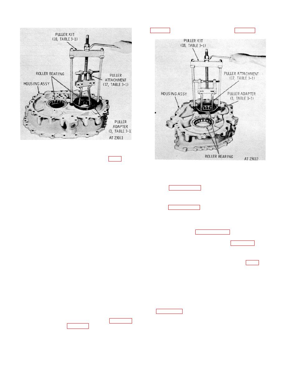
Figure 7-45. Removing roller bearing from right
output housing assembly.
b.
Figure 7-46. Removing roller bearing from left output
(1) Do not remove brake and steer
housing Assembly.
coolant pressure retaining valve assembly, items (48
through 51), unless replacement of parts is necessary.
7-118. Cleaning
If necessary, remove spring guide (48), spring (49),
valve (50) and valve seat (51).
Refer to paragraph 5-2 for cleaning recommendations.
(2) Do not remove roll pin (54) unless
replacement is necessary. If necessary, remove the pin.
7-119. Inspection and Repair
(3) Do not remove insert staking pins (52
Refer to paragraph 5-3 for general inspection and repair
and 57) and screw thread inserts (53 and 56) unless
recommendations.
replacement is necessary. If necessary, remove the
pins and inserts.
(4) Do not remove plugs (59) unless
7-120. Repair Standards
replacement is necessary. If necessary, remove the
plugs.
repair standards.
(5) Do not remove two dowel pins (58)
unless replacement is necessary. If necessary, remove
the pills.
7-121. Assembly
(6) Do not remove three plugs (60) unless
replacement is necessary. If necessary, remove the
a.
Right Output Housing Assembly (FO-8).
plugs.
(1) If plugs (64, 65, and 66) were
(7) Remove five output clutch sleeve
removed, install them.
bolts (62) and five flat washers (61). Flatten tab
(2) If dowel pins (67 and 73) were
lockwasher (93) and remove retaining bolt (92), tab
removed, install new replacements. Press the pins to
lockwasher (931) and roller bearing retaining plate (94).
0.300 inch above the surface of housing (63).
(8) Remove
output
clutch
sleeve
(3) If screw thread inserts (69, 71 and 74)
assembly (41) with two sealrings 4(0).
Remove
and staking pins (68, 72 and 75) were removed, install
sealrings (40) from sleeve assembly (41).
new replacement parts. Install to the dimensions given
(9) Do not remove reduction drive gear
in figure 7-47. Use a bolt with the same thread size as
roller bearings (63 and 95) unless replacement is
the inner thread of the insert, and a sleeve with an
necessary. If necessary, use adapter (3, table 3-1),
puller attachment (17, table 3-1), and puller kit (18,
7-38
|
|
Privacy Statement - Press Release - Copyright Information. - Contact Us |