 |
|||
|
|
|||
|
Page Title:
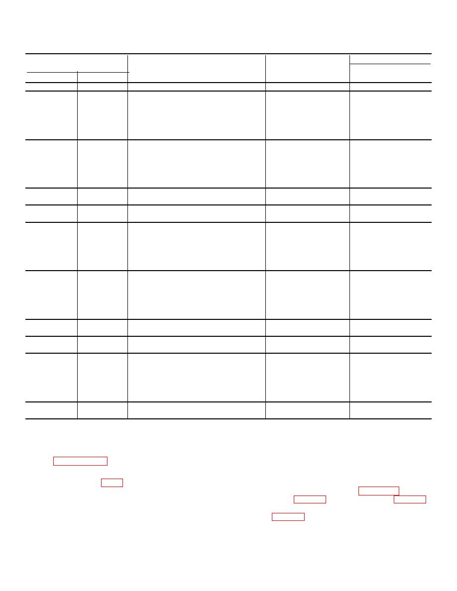
Table 7-17. Repair Standards (Right, Left Output Housing) |
|
||
| ||||||||||
|
|
 TM 9-2520-249-34& P
Table 7-17. Repair Standards (Right, Left Output Housing)
Wear limit
Reference
Size and fit
DS/GS
Foldout
Item
Point of measurement
of new parts
maintenance
7
42a
Inside diameter of sleeve insert at seals
2.875 to 2.877
2.879
7
55a
Inside diameter at bearing surface of ...
5.5106 to 5.5118
5.5123
housing ................................ ................
7
63a
Outside diameter of bearing .................
5.5133 to 5.5141
*
7
55a
Fit of bearing in housing .......................
0.0015T to 0.0035T
63a
7
55b
Inside diameter at bearing surface of ...
5.5106 to 5.5118
5.5123
housing
7
95a
Outside diameter of bearing .................
5.5133 to 5.5141
*
7
55b.
Fit of bearing in housing .......................
0.001IT to 0.0035T
*
95a
7
55c
Inside diameter of housing at sealrings .
12.500 to 12.506
12.510
7
55d
Outside diameter of housing at sealrings
10.496 to 10.500
10.492
8
21a
Outside diameter of bearing .................
5.5133 to 5.5141
*
8
63a
Inside diameter at bearing surface of ....
5.5106 to 5.5118
5.5123
housing ................................ ................
8
21a,
Fit of bearing in housing .......................
0.0015T to 0.0035T
63a
8
36a
Outside diameter of bearing .................
5.5133 to 5.5141
*
8
63b
Inside diameter at bearing surface of ....
5.5106 to 5.5118
5.5123
housing ................................ ................
8
36a,
Fit of bearing in housing .......................
0.0015T to 0.0035T
63b
8
63c
Inside diameter of housing at sealrings .
12.500 to 12.506
12.510
8
63d
Outside diameter of housing at sealrings
10.496 to 10.500
10.492
8
63e
Inside diameter at bearing bore of outer
0.686 to 0.687
0.6875
housing ................................ ................
8
70a
Outside diameter of needle bearing ......
0.6875 basic
8
63e,
Fit of bearings in outer housing .............
Press fit
70a
8
90a
Inside diameter of sleeve insert at seals
2.875 to 2.877 2.879
*Replace when worn beyond new dimensions.
Section XXI. LEFT OUTPUT END COVER ASSEMBLY-REPAIR
c. Do not remove reduction drive and driven
7-122. Description
gear roller bearings (69 and 85) from output end cover
Refer to paragraph 2-26 for description of the left output
(81), unless replacement is necessary. If necessary,
end cover assembly.
flatten tab lockwasher (87) and remove bolt (88), tab
lockwasher (87) and retaining plate (86).
a. Do not remove oil seal (78) from output
attachment (17, table 3-1), and puller kit (18, table 3-1),
end cover (81), unless replacement is necessary. If
remove the reduction drive and driven gear roller
necessary, remove the seal.
bearings (fig. 7-48).
b. Do not remove sleeve (80) from output end
cover (81).
unless replacement is necessary.
If
necessary, remove the sleeve.
7-40
|
|
Privacy Statement - Press Release - Copyright Information. - Contact Us |