 |
|||
|
|
|||
|
Page Title:
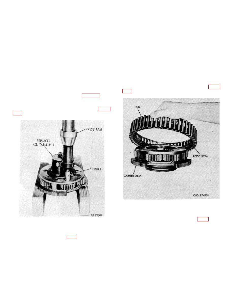
Figure 7-28. Installing spindle into reverse-range planetary carrier. |
|
||
| ||||||||||
|
|
 TM 9-2520-249-34& P
Stake carrier metal over the pin at two places.
a. If the six pins (37) were removed, install
i.
Install the remaining five pinions, each with
new ones. Press the pins into the carrier, to 0.010 inch
its associated parts, and pins (39.8) into the carrier as
below the plug bore surface of carrier (38). Stake metal
described in b through h, above.
over each plug at two places.
j.
Install retaining ring (40) into the hub of
b. Grease the bore of a pinion (39.4) with a
planetary carrier assembly (36).
liberal amount of oil-soluble grease.
k. Install bearing (34) into the hub of carrier
c. Install a spacer (39.3) and a thrust washer
assembly (36). Press the bearing until it is firmly seated
(39.2) on one side of pinion (39.4).
against retaining ring (40).
d. Install 25 pinion rollers (39.5) inside pinion
l.
Install retaining ring (33) into the hub of
(39.4) around the bore wall.
carrier assembly (36).
e. Install another spacer (39.6) and another
m. Install retaining ring (44) into reverse-range
thrust washer (39.7) on the other end of pinion (39.4).
clutch hub (43).
f.
Install the pinion with rollers, washers and
n. Install hub (43) with retaining snap ring (44)
spacers into the carrier, using alining tool of replacer
onto reverse-range carrier assembly (36), Refer to figure
(22, table 3 1) to aline the pinion components with the
spindle bore in the carrier.
indexing the spindle and replacer, install the spindle into
the carrier. Press the spindle flush with, to 0.010 inch
below, the spindle bore of the carrier. Refer to figure
Figure 7-29. Installing reverse-range clutch hub onto
carrier assembly.
Figure 7-28. Installing spindle into reverse-range
reverse-range clutch hub (43).
planetary carrier.
p. Install two sealrings (41 and 42) onto the
hub of reverse-range carrier assembly (36). Retain
them with soluble grease.
to 0.090 inch below the pin bore surface of carrier (38).
7-25
|
|
Privacy Statement - Press Release - Copyright Information. - Contact Us |