 |
|||
|
|
|||
|
|
|||
| ||||||||||
|
|
 TM 9-2520-249-34& P
7-93.
Disassembly
a. Remove two sealrings (41 and 42) from the
hub of reverse-range carrier assembly (36).
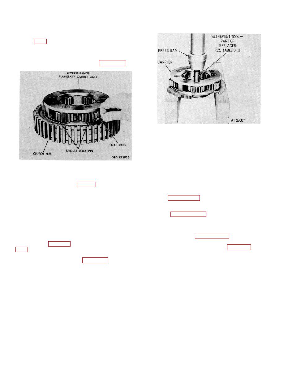
b. Remove retaining snap ring (35), retaining
reverse-range clutch hub (43). Refer to figure 7 26.
Figure 7-27 Pressing spindle from reverse-range
planetary carrier.
NOTE
The pinions are a matched set.
Therefore, each pinion and its
component parts should be placed in
Figure 7-26. Removing (or installing ) retaining snap
a separate container. If one of the
ring which retains reverse-range clutch hub.
pinions must be replaced, the entire
set of six must be replaced.
(44) from the hub.
7-94. Cleaning
d. Remove retaining rings (33 and 40) from
Refer to paragraph 5-2 for cleaning recommendations.
carrier assembly (36).
e. Remove bearing assembly (34) from
7-95. Inspection and Repair
carrier assembly (36).
Refer to paragraph 5-3 for inspection and repair
f.
Remove six pins (39.8) from carrier (38),
recommendations.
driving them toward the inside of the carrier.
g. Do not remove pins (37) from carrier (38)
7-96.
Repair Standards
unless replacement is necessary.
h. Using an alinement tool of replacer
repair standards.
assembly (22, table 3-1), remove six spindles (39.1.
39.7), 12 spacers (39.3 and 39.6) and 150 pinion rollers
7-97.
Assembly (FO 9)
(39.5) from carrier (38) Refer to figure 7-27.
NOTE
Chill spindles (39.1) in dry ice for
approximately 1 hour prior to
installing in the carrier.
7-24
|
|
Privacy Statement - Press Release - Copyright Information. - Contact Us |