 |
|||
|
|
|||
|
Page Title:
Section XII. BEVEL GEAR HOUSING ASSEMBLY-REPAIR |
|
||
| ||||||||||
|
|
 TM 9-2520-249-34&P
Table 7-9. Repair Standards (Right, Left Cross-Shaft Bearing Retainers) - Continued
Wear limit
Reference
Size and fit
DS/GS
Foldout
Item
Point of measurement
of new parts
maintenance
5
21a
Inside diameter at bearing surface of ...
4.9930 to 4.9940
4.9945
retainer
5
46a
Outside diameter of bearing outer race .
5.000 to 5.0010
*
5
21a
Fit of bearing outer race in retainer .......
0.0060T to 0.0080T
46a
5
21b
Outside diameter of bearing retainer at
6.246 to 6.250
6.242
sealrings
5
22a
Inside diameter of sleeve bearing at......
5.000 to 5.002
5.0040
sealring
*Replace when worn beyond new dimensions.
Section XII. BEVEL GEAR HOUSING ASSEMBLY-REPAIR
necessary, or to aid in cleaning the housing.
7-68. Description
d. Do not remove dowel pins (13, 14, 15, and
Refer to paragraph 2-25 for a description of the bevel
17) unless replacement is necessary.
gear housing components.
7-70. Cleaning
Refer to paragraph 5-2 for cleaning recommendations.
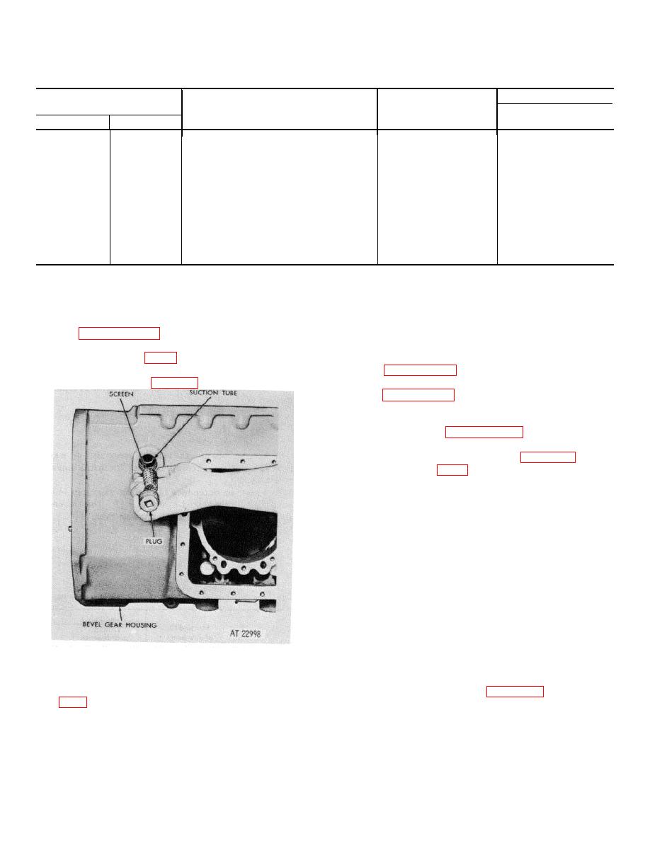
a. Remove plug and output pump screen from
7-71. Inspection and Repair
the bevel gear housing (fig. 7-15).
Refer to paragraph 5-3 for general inspection and repair
recommendations.
7-72. Repair Standards
repair standards.
a. If dowel pins (13) were removed, press
replacements into housing (9), so that they extend 0.30
inch above the housing surface.
b. If dowel pins (14, 15 and 17) were
removed, press replacements into housing (9), flush
with, to 0.03 inch below, the housing surface and stake
metal over the pins.
c. If dowel pins (18) were removed, press
replacements into housing (9), so that they extend 0.20
inch above the housing surface.
d. If plugs (11 and 12) were removed, install
the plugs.
e. If output pump suction tube (16) was
removed from housing (9), install a new replacement.
Press the tube until the shoulder of the tube is firmly
Figure 7-15. Removing (or installing) plug and output
seated in the housing.
pump screen.
f.
Install output pump screen (26) and plug
b. Do not remove output pump suction tube
(27) into housing (9). Refer to figure 7-15.
(16. FO-5) unless replacement is necessary.
c. Do not remove plugs (10, 11 and 12) from
bevel gear housing 19) unless replacement is
7-16
|
|
Privacy Statement - Press Release - Copyright Information. - Contact Us |