 |
|||
|
|
|||
|
|
|||
| ||||||||||
|
|
 TM 9-2520-246-34
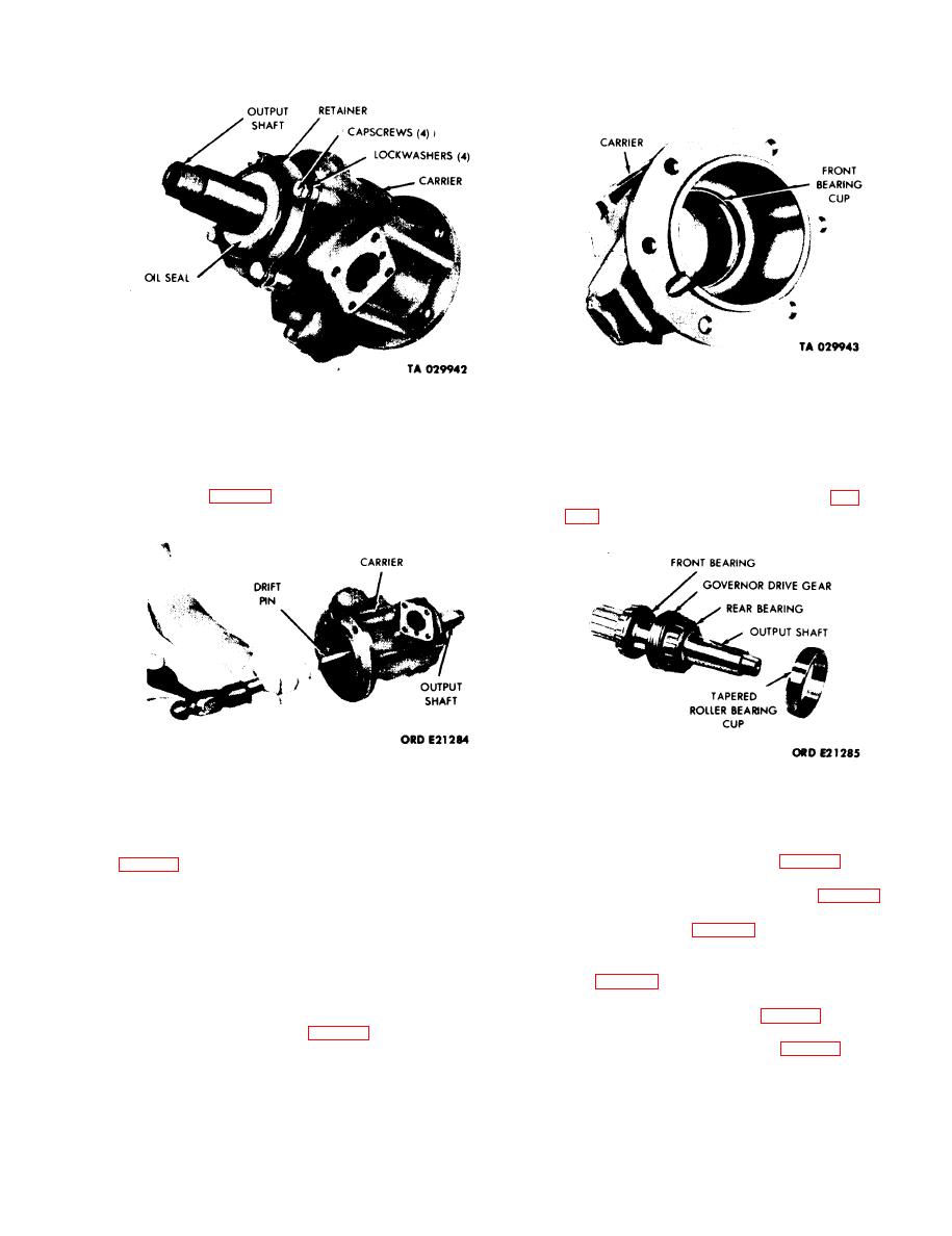
Figure 5-34. Removal of Output Shaft Front Bearing
Cup.
Figure 5-32. Removal of Output Shaft Rear Bearing
Retainer and Oil Seal.
NOTE
d. Output Shaft. Use a soft drift pin and hammer
Upon assembling the output shaft, make
to drive the output shaft and both bearings from the
sure rear bearing, governor drive gear, and
carrier. (See fig. 5-33.) Removal of the output shaft
front bearing are installed as shown in fig.
will also remove the rear tapered roller bearing cup.
Figure 5-33. Removal of Output Shaft, Both Bearings,
Figure 5-35. Disassembly of Output Shaft.
and Rear Tapered Roller Bearing Cup.
5-27. Assembly Sequence.
e. Output Shaft Front Bearing Cup. Place the
carrier and front bearing cup in an arbor press. (See
NOTE
Upon assembly, make sure the bearing cup
is installed with the taper of the cup facing
d. Output shaft rear bearing cup, retainer, and oil
toward the center of the carrier.
seal. (See fig. 5-32.)
f. Output Shaft. Using an arbor press, press the
governor drive gear, rear bearing, and front bearing
from the output shaft. (See fig. 5-35.)
5-19
|
|
Privacy Statement - Press Release - Copyright Information. - Contact Us |