 |
|||
|
|
|||
|
Page Title:
Section VI. REPAIR (MODEL WND-7-28) |
|
||
| ||||||||||
|
|
 TM 9-2520-246-34
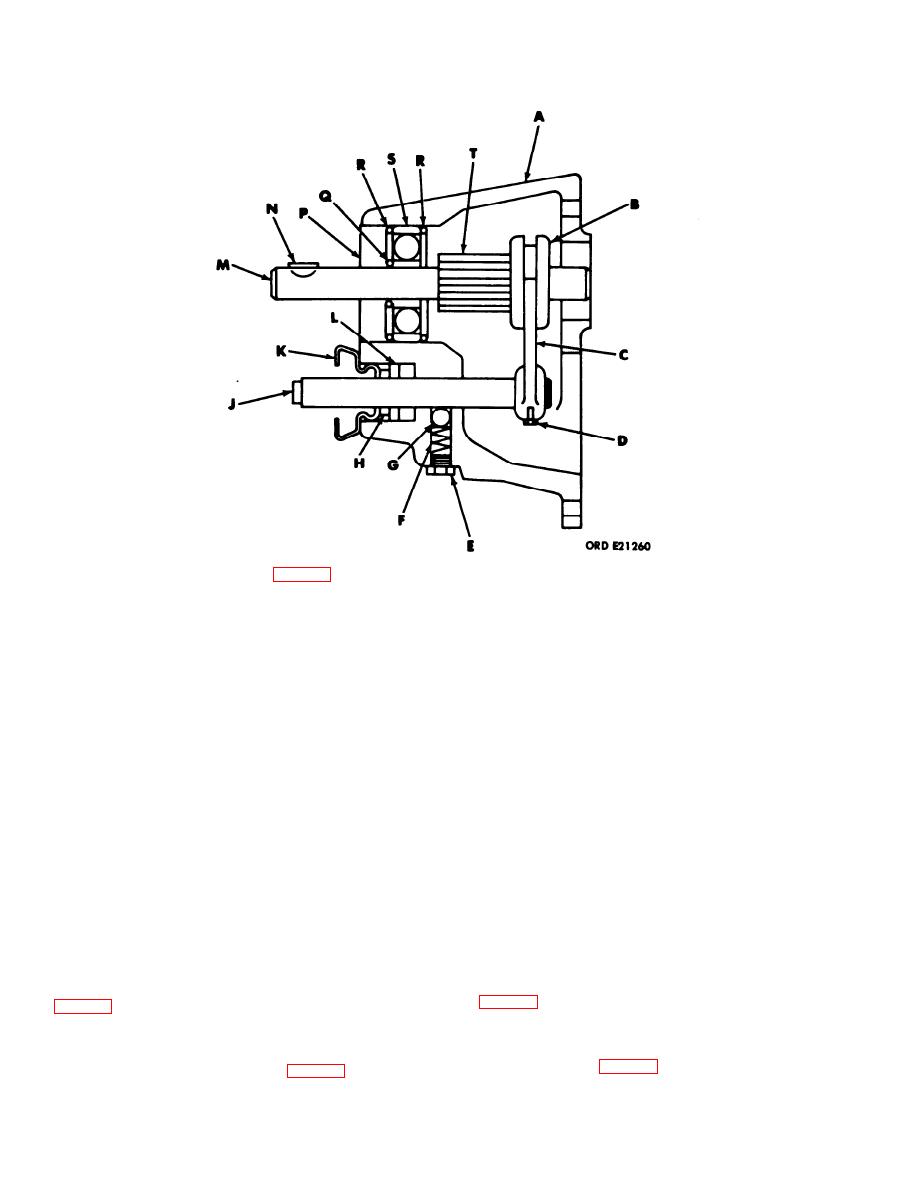
Legend for fig. 5-20:
ITEM
KEY
ITEM
KEY
Boot
K
Housing
A
Oil seal
L
Sliding clutch sleeve
B
Output shaft
M
Shifter fork
C
Key
N
Fork locking screw
D
P
Oil seal
Retainer
E
Snapring
Spring
F
Q
Snapring
R
Ball
G
Bearing
S
Retainer
H
Output shaft gear
T
J
Shifter shaft
Figure 5-20. Rear Output Shaft Housing --
Sectional View.
Section VI. REPAIR (MODEL WND-7-28)
NOTE
5-16. Disassembly and Assembly of Accessory
Drive.
During assembly, always install a new
gasket.
a. Rear Output Shaft Housing and Shifter Shaft
Retainer, Ball, and Spring.
b. Shifter Shaft and Shifter Shaft Fork.
(1) Remove the five capscrews securing the rear
(1) Cut safety wire and remove from housing.
output shaft housing to the power takeoff case. (See
(See fig. 5-22.)
Discard the gasket.
(2) Remove the lock screw securing the shifter
fork to the shifter shaft and remove the shaft and fork
(2) Remove the retainer, spring, and ball from
from the housing. (See fig. 5-22.)
the rear output shaft housing. (See fig. 5-21.)
5-12
|
|
Privacy Statement - Press Release - Copyright Information. - Contact Us |