 |
|||
|
|
|||
|
Page Title:
Section VIII. REPAIR AND REPLACEMENT STANDARDS (MODEL T-136-21) |
|
||
| ||||||||||
|
|
 TM 9-2520-246-34
drag when turned by hand. If test indicates bearings
assemblies are turned by hand from inside the case.
are too tight or too loose, shims must be added or
Position cover on case and secure with four capscrews
removed as directed in b below.
and lockwashers. Tighten to 60-77 lb-ft torque.
c. Add Shim. When slight drag adjustment has
b. Add or Remove Shims. Remove four capscrews
and lockwashers holding the idler shaft rear bearing
been obtained, remove cover and add one 0.005-inch
cover (fig. 4-35) to case. Remove cover and add or
shim. Install cover (b above). This will provide and
remove shims as required to obtain a slight drag when
ensure the proper end play.
Section Vlll. REPAIR AND REPLACEMENT STANDARDS
(MODEL T-136-21)
4-33. GeneraI. The repair and replacement
plane. If three or more sprags are worn to
standards included herein provide the minimum,
a size 0.375 inch or smaller, replace sprag
maximum, and key clearances of new parts. (See fig.
unit with new sprags.
tables 4-5, 4-6, 4-7, and 4-8.) Standards also provide
a. Since the wear on all sprags in any one sprag
wear limits which indicate the point to which a part or
unit will be quite uniform, it is only necessary to
parts may be worn before replacement is required, in
inspect two or three sprags in each assembly.
order to receive maximum service with minimum
replacement. Normally, all parts which have not been
b. Inspect the sprags for evidence of wear on the
worn beyond the dimensions shown in the "Wear
cam surface which contacts the inner race. If the wear
Limits" column, or damaged by corrosion, will be
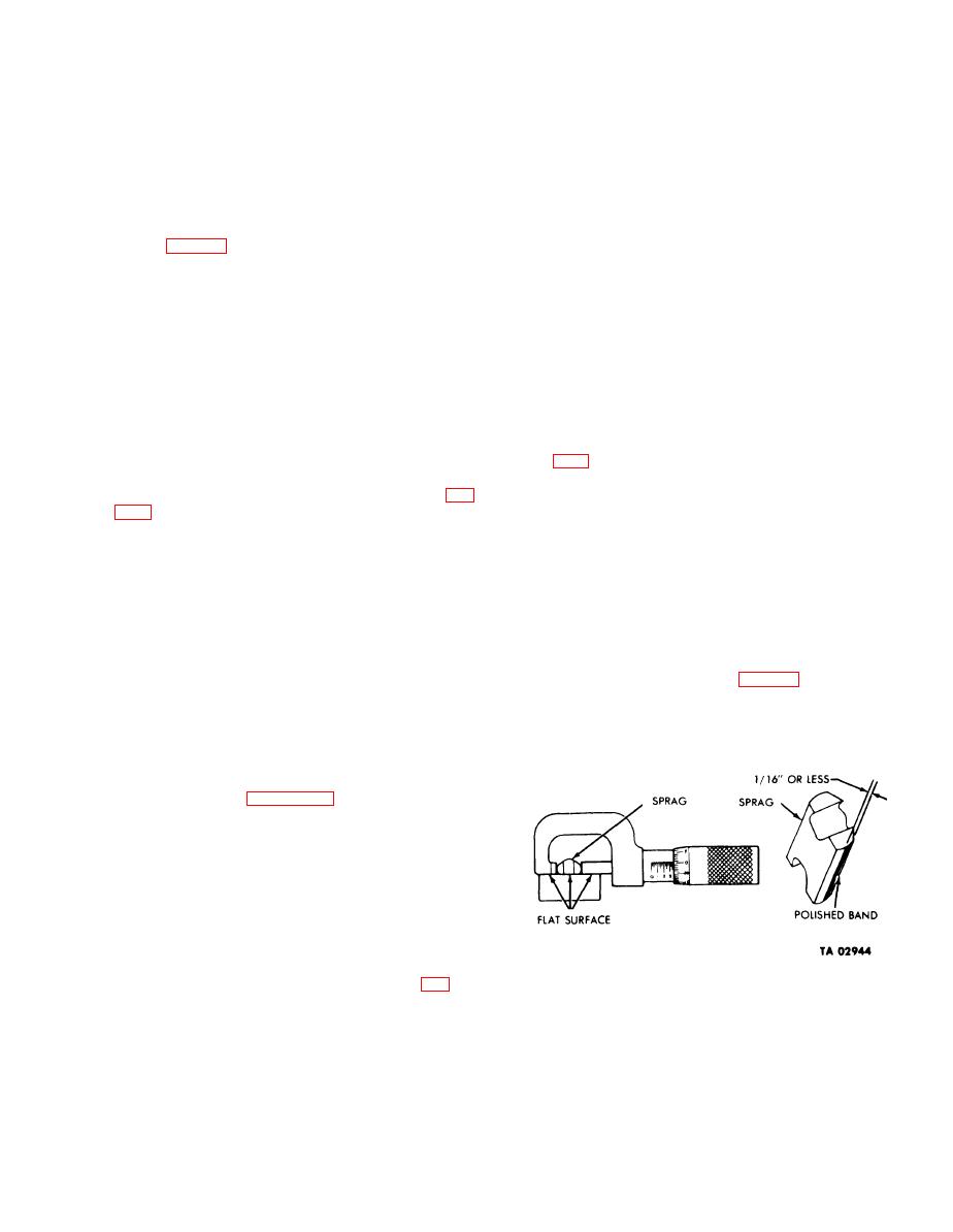
on the inner edge of the sprag is not more than 1/16
approved for service. An asterisk (*) in the "Wear
of an inch wide, the sprag is still usable. This
Limits" column. indicates that the part or parts should
inspection procedure is shown in fig. 4-46.
be replaced when worn beyond the limits given in the
"Size and Fit of New Parts" column. In the "Size and
c. Inspect the energizing springs for evidence of wear,
Fit of New Parts" and "Wear Limits" column, the
kinking, or twisting. If any of the above defects are
letter L indicates a loose fit (clearance) and a letter T
present, replace the spring with a new one.
indicates a tight fit (interference).
4-34. Repair and Replacement Standard Points
4-50. and corresponding tables 4-5, 4-6, 4-7 and 4-8,
provide the repair and replacement standard points of
measurement for transfer model T-136-21.
4-35. Sprags and Energizing Springs.
NOTE
When checking sprags, the anvil end and
spindle of the micrometer and flat backs of
the sprag must all rest on a flat surface (fig.
Figure 4-46. lnspecting Sprags for Wear.
4-31
|
|
Privacy Statement - Press Release - Copyright Information. - Contact Us |