 |
|||
|
|
|||
|
|
|||
| ||||||||||
|
|
 TM 9-2520-246-34
CHAPTER 4
REPAIR OF TRANSFERS
Section I. DESCRIPTION, OPERATION, AND DATA
(MODEL T-136-27)
and outer brakeshoe and lever assembly is supported
4-1. General. This chapter provides the repair
on the transfer rear output rear bearing cover.
instructions for positive locking transfer model T-136-
27. (See fig. 4-1 and 4-2.)
b. Operation. The selection of high or low range in
the transfer is accomplished by a shifting mechanism,
4-2. Description and Operation.
which moves the synchronizer into contact with the
input-shaft low-speed gear or the input-shaft high-
speed gear. With positive locking engaged, power is
a. Description. The positive locking transfer is a
distributed to front and rear axles when transmission
two-speed synchromesh unit with front and rear
is placed in the selected gear.
output shafts. The transfer unit is driven by the
regular 5-speed transmission through a propeller shaft.
(1) Low Range. When the transfer is shifted to
Low or high gear selection through the transfer gives
low range, the synchronizer assembly is moved
the truck a total of ten forward gears, and two reverse
forward on the input shaft to engage the input-shaft
gears. With the operation of an air selector valve (fig.
low-speed gear which is in mesh with the countershaft
low-speed gear. Because the low-speed gear is keyed to
shaft to the rear output shaft to drive the front axle.
the countershaft, the power flow is through the
The transfer distributes the power to front and rear
countershaft gears, to the rear (and front if lock-up
axles through the propeller shafts. The handbrake
assembly is engaged) output-shaft gears and to the
drum is mounted in the transfer rear output shaft
companion flanges.
companion flange. (See fig. 4-2.) The handbrake inner
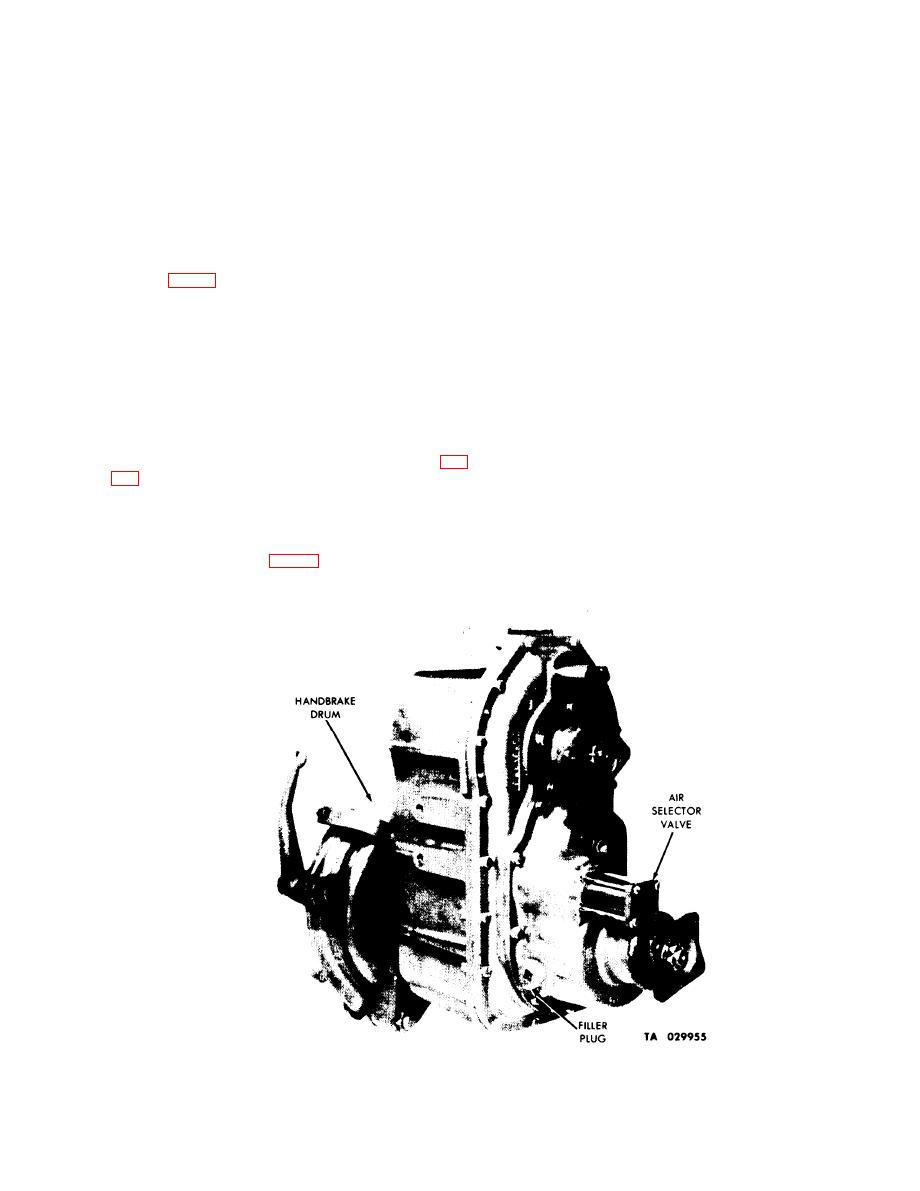
Figure 4-1. Positive Locking Transfer Model T-136-27 -- Front View.
4-1
|
|
Privacy Statement - Press Release - Copyright Information. - Contact Us |
