 |
|||
|
|
|||
|
Page Title:
Section IV. COMPARISON STANDARDS |
|
||
| ||||||||||
|
|
 TM 750-245-4
allowed on system drawings and as permitted by
m. Dewetting. (Separation of printed circuit from
Department of the Army publications for system
circuit board.)
material.
n. Insufficient solder.
r. Plated through holes not filled with continuous
o. Visible bare primary conductor within the solder
solder plug.
joint area.
s. Pads connected by plated-through holes and
p. Clinched leads resulting in a reduction of the
eyelets connecting pads on multi-layer boards or double
required spacing between conductors.
sided printed circuit boards show evidence of failure to
q. Splicing of conductors is prohibited, except as
wet the metallic surfaces.
Section IV. COMPARISON STANDARDS
7-12. General
and bad workmanship. The remaining tables show
This section provides a visual guide for inspection of
actual repair procedures with applicable inspection
solder connectors.
These show the acceptable,
criteria.
minimum acceptable, and reject inspection criteria.
Table 7-3. Workmanship
Indicator
Illustration
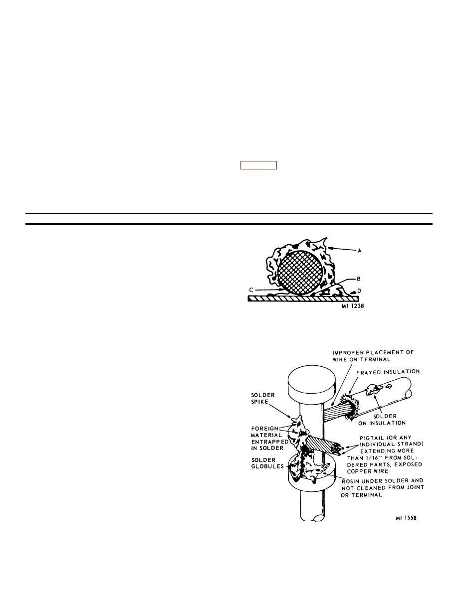
Cold or underheated solder joint
A. Solder has a chalky appearance, lacks metallic
luster, generally presents a rough, piled-up
appearance.
B. Solder has not bonded terminal and wire
together.
C. Solder coverage not complete.
D. Improper filleting indicating insufficient flowing
and watting action.
Improper soldering
7-9
|
|
Privacy Statement - Press Release - Copyright Information. - Contact Us |