 |
|||
|
|
|||
|
|
|||
| ||||||||||
|
|
 TM 750-245-4
4-14. Key Type Insert Installation
The installation of key type inserts is very simple and
can be accomplished without special tools. After hole
preparation (fig. 4-2) or old key insert removal (fig. 4-4)
screw the new key insert (fig. 4-5) to a depth of 0.010 to
0.030 below the surface. Drive the keys down (fig. 4-6)
to set and lock the insert.
4-15. Blind Nut Assemblies (Fig. 4-6)
The inspector will have to perform an in-process
inspection of blind nut installations because in most
cases they cannot be inspected after repair. Refer to
installation of blind nuts.
4-16. Hardware Inspection
All hardware shall be of the proper size, type, shape,
length, and thread. There shall be no burrs, corrosion or
physical damage. Washers shall have correct pileup.
Screws shall protrude at least one complete thread from
the surface of the hex or clinch nut. Screws shall not
protrude more than two complete threads from the
surface of the hex or clinch nut when there is a
possibility of shorting, mechanical interference, or safety
hazard.
a. Threaded Components (Bolts, Screws, and
Nuts).
(1) Threads shall not be crossed or stripped.
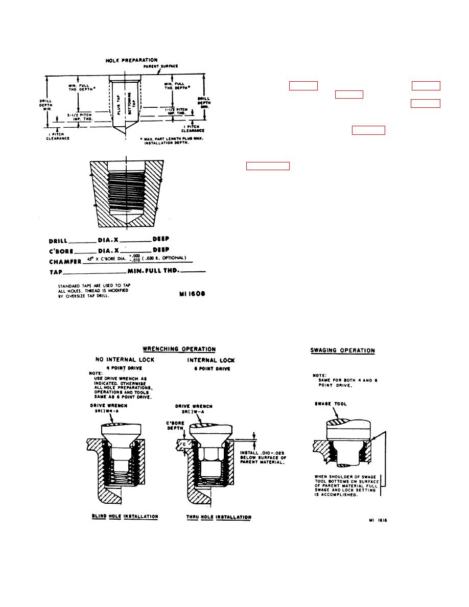
Figure 4-2. New hole preparation.
(2) Bolt shanks shall not be galled.
Figure 4-3. Swaging type insert installation.
4-4
|
|
Privacy Statement - Press Release - Copyright Information. - Contact Us |