 |
|||
|
|
|||
|
Page Title:
"Not Go" Gages for Screw Threads |
|
||
| ||||||||||
|
|
 TM 750-245-4
checks the maximum limit of a threaded plug and the
minimum pitch diameter of the screw. The tolerance is
minimum limit of the threaded hole.
plus but may be minus for the reason given in the
preceding subparagraph.
a. Pitch Diameter. The pitch diameter of W and X
"Go" plug gages is the same as the minimum pitch
diameter of the threaded hole or nut. The Tolerance is
4-10. Thread Form on Gages
plus for plugs. The pitch diameter of the W and X "Go"
ring gages is the same as the maximum pitch diameter
and ring gages. The crest of the thread on "Not Go"
of the screw. The tolerance is minus for rings.
plug and ring gages is partly removed to insure proper
contact. There is also a clearance groove at the root of
b. Major and Minor Diameters.
The major
"Not Go" plug and ring gages to insure pitch diameter
diameter of the "Go" plug gage is the same as the basic
contact. The "Go" plug and ring gages may have
major diameter, with a plus tolerance. The minor
clearance grooves at the roots to facilitate grinding and
diameter of the "Go" ring gage is the same as the
lapping.
minimum minor diameter of the nut or tapped hole, with
a minus tolerance.
4-11. Truncated Setting Plugs
a. The major diameter of the full portion of the
"Go" setting plug is that of a full American National
form, based on maximum pitch diameter of the screw.
The tolerance is plus. The major diameter of the
Truncated portion of the "Go" setting plug is that of a full
American National form minus one-third the basic
thread depth with a minus tolerance.
b. The major diameter of the full portion of the
"Not Go" setting plug is the same as that of the "Go"
plug of the same nominal size, except that the
truncation from a theoretical vee should not be less than
0.058 times pitch. The latter condition might arise in the
case of fine pitches and especially wide tolerances. The
tolerance is minus. The major diameter of the truncated
portion of the "Not Go" setting plug is that of a full
American National form minus one-third the basic
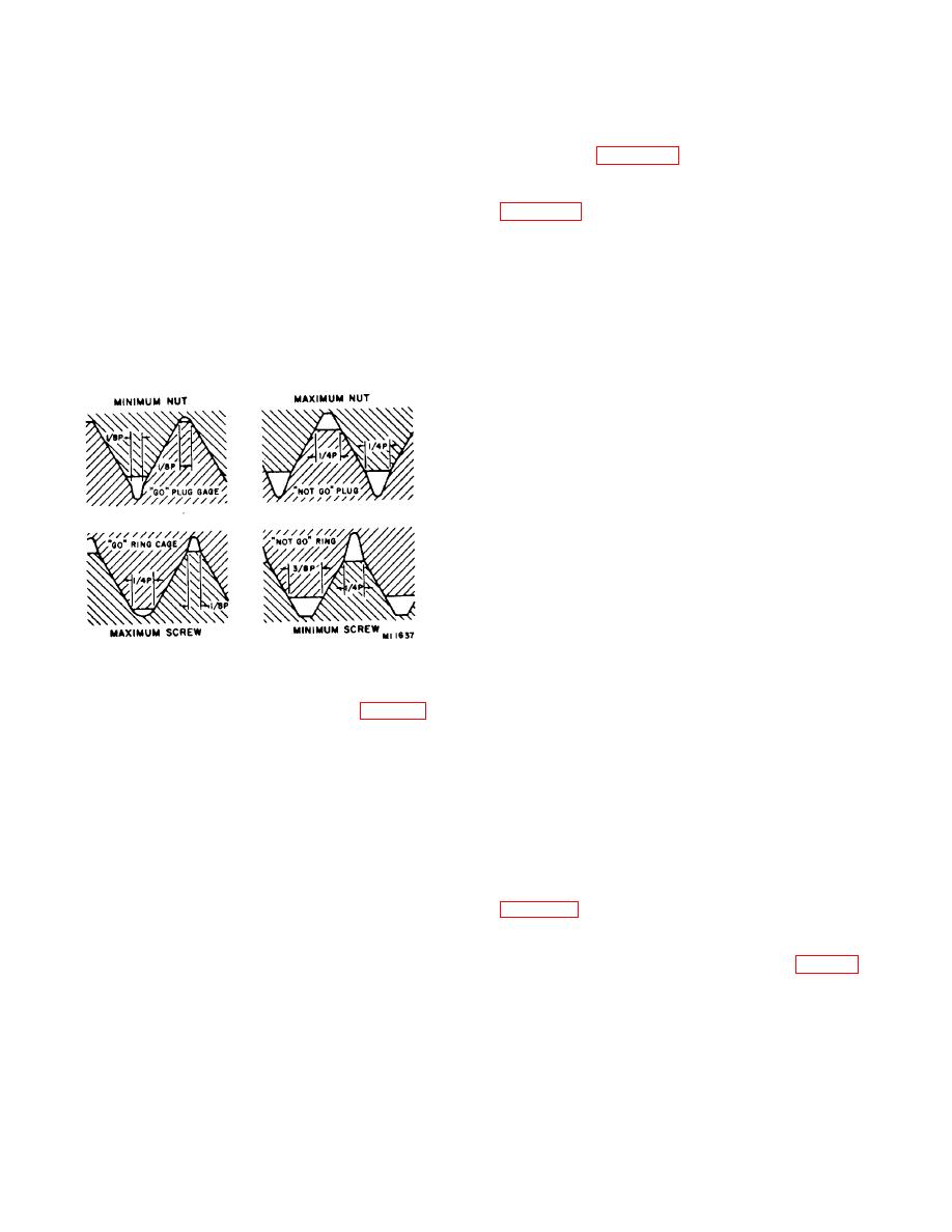
Figure 4-1. Screw thread check.
thread depth, with a minus tolerance.
4-9. "Not Go" Gages for Screw Threads (Fig. 4-1)
4-12. Inserts
A "Not Go" thread gage which checks the pitch diameter
a. The inspector should familiarize himself with the
only, usually meets practical requirements. The "Not
repair procedures, as in-process inspection should be
Go" gage checks the minimum limit of a threaded plug
performed to insure a good insert installation. Refer to
and the maximum limit of a threaded hole.
the system documentation to determine if such repairs
a. Pitch Diameter Plug Gage. The pitch diameter
are authorized and the number of times the insert can
of a "Not Go" plug gage equals the maximum pitch
be replaced.
diameter of the threaded hole or nut. The tolerance is
b. There are various types of inserts which can be
minus but may be plus. All gages used for the
used to repair components which have attaching hole
production of screw threads, and "Go" gages for
threads stripped. New hole preparation as shown in
inspection, should be within the extreme limits of the
product. However, to avoid needless controversy about
installation.
parts close to "Not Go" limits because of possible small
differences in gage sizes, the pitch diameter tolerances
on all "Not Go" gages used for final inspection and for
4-13. Swaging Type Insert Installation (fig. 4-3)
inspection of purchased products, may be outside of the
The installation of swaging type inserts requires special
product limits is specially authorized.
tools. A drive wrench is used to install the insert into the
tapped hole. After the insert is installed to the proper
b. Pitch Diameter Ring Gage. The pitch diameter
depth a swage tool is then used to lock the insert in
of the "Not Go" thread-ring gage is the same as the
place.
4-3
|
|
Privacy Statement - Press Release - Copyright Information. - Contact Us |