 |
|||
|
|
|||
|
Page Title:
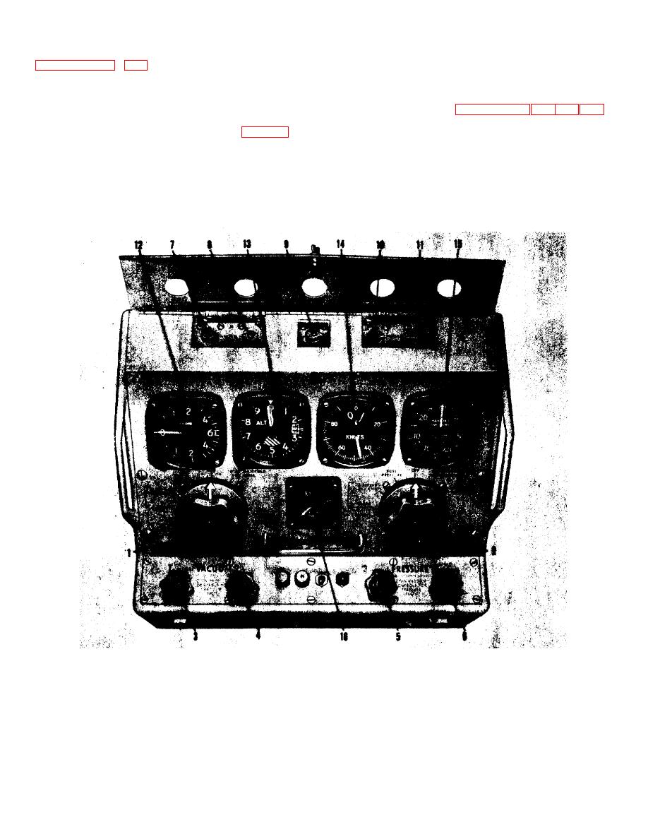
Figure 5-3. Instruments, Controls and Valves |
|
||
| ||||||||||
|
|
 TM 55-4920-416-13
Section V
NAVAER 17-15C-539
5-16. SELFCHECK. The performance and condition of the
having oil in the pressure lines causing
VPT-7A test set is readily checked by performing the
possible damage to instruments and
selfchecks as described in paragraphs 4-52, 4-55, 4-59, 4-64.
valves.
To check the power supply in operation, refer to figure 1-6 and
5-17. OVERHAUL
AND
RECALIBRATION.
It
is
proceed as follows:
recommended that the test set should be returned for
a. Throw power switch to ON.
recalibration and/or overhaul annually.
b Connect a voltmeter (20,000 Ω/volt) between any
exposed screw on the motor assembly and to the terminal
marked with a red dot on top of the electrolytic capacitor; the
voltage Indicated on the voltmeter should be between
23 to 33 V dc.
1.
Vacuum Selector Valve
9.
Case Leak Test Valve
2.
Pressure Selector Valve
10.
Case Leak Test Valve
3.
Vacuum Decrease Valve
11.
Case Leak Test Valve
4.
Vacuum Increase Valve
12.
Rate-of-Climb Indicator
5.
Pressure Increase Valve
13.
Altimeter
6.
Pressure Decrease Valve
14.
Airspeed Indicator
7.
Case Leak Test Valve
15.
Manifold Pressure Indicator
8.
Case Leak Test Valve
16.
Fuel Pressure Indicator
Figure 5-3. Instruments, Controls and Valves
24
|
|
Privacy Statement - Press Release - Copyright Information. - Contact Us |
