 |
|||
|
|
|||
|
Page Title:
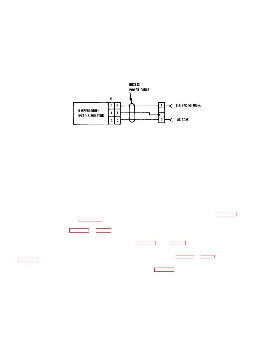
FIGURE 4-11. Simulator Power Connection |
|
||
| ||||||||||
|
|
 TM 55-4920-411-13&P
( t ) anti
3 (-) (figure FO-1). Voltage shall measure 12.0
h. If result is not as specified, check continuity of
0.6 vdc. If not, perform Troubleshooting Table 4-3 and
fuse (1/2A), power lamp, and POWER switch in on posi-
fig FO-1 as applicable.
tion. If open, replace fuse (58, figure 4-12) power lamp
(61) or POWER switch (56). Check for broken or loose
k. If SECONDS display starts running when power
is applied to simulator and cannot be reset with
START/STOP, RESET switch. See Troubleshooting
i. If power lamp lights and SECONDS display does
not light, measure 5-volt nonregulated supply between
reference points E and F, and fig F0-1. Voltage shall
1. Press LAMP TEST switch. Lamps through L6
measure 5.0 0.5 vdc. If not, perform Troubleshooting
m. If some, but not all, lamps light, see Trouble-
j. If power lamp lights and SECONDS display does
not light, measure 12-volt supply between test points 2
|
|
Privacy Statement - Press Release - Copyright Information. - Contact Us |