 |
|||
|
|
|||
|
Page Title:
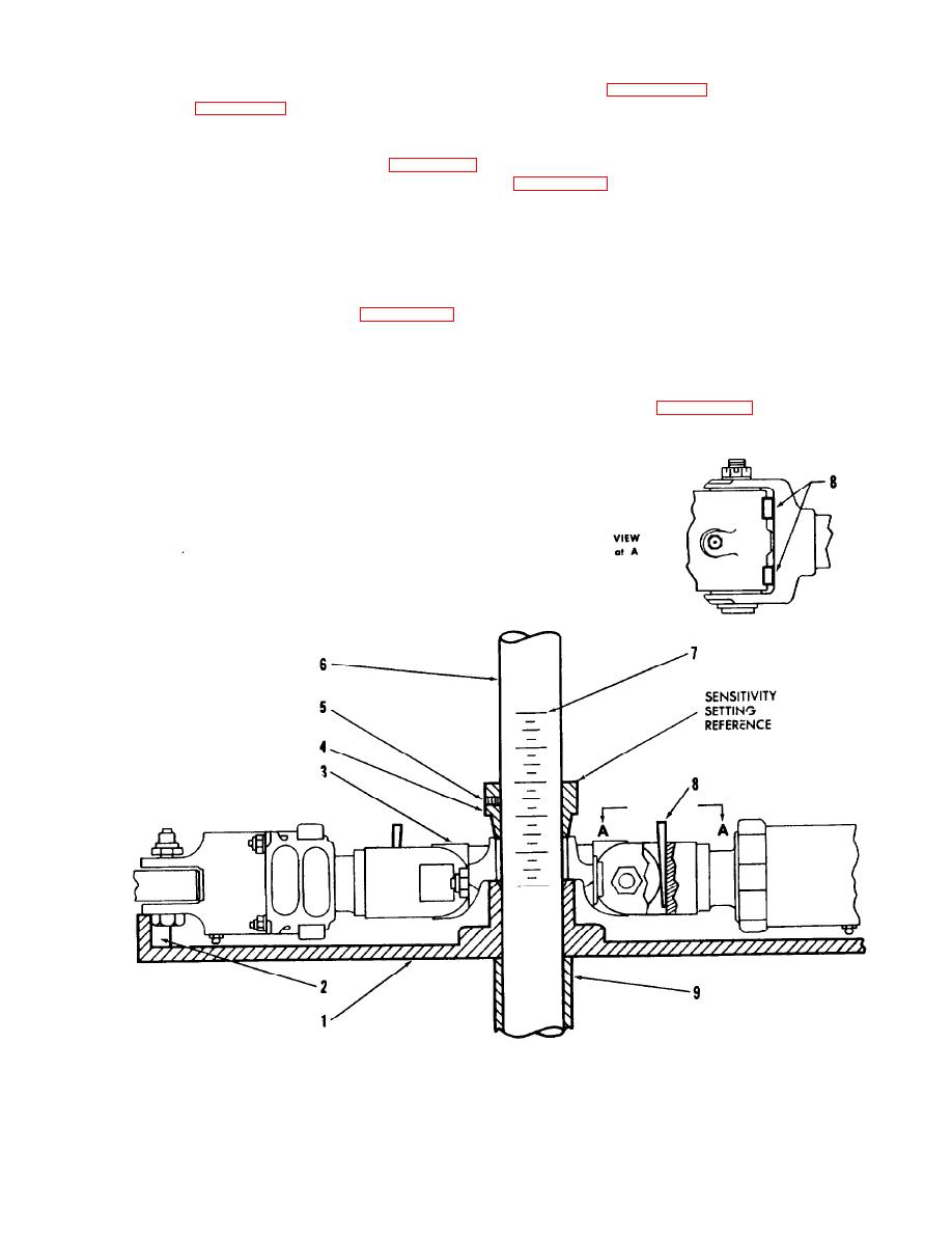
Figure 4-37. Balancer Installation - CH-34 Helicopter Tail Rotor Hub and Blade Assembly |
|
||
| ||||||||||
|
|
 TM 55-4920-201-14
wedges (8, figure 4-37), symmetrically spaced
tightening bushing setscrew (5) with 1/8-inch hex
wrench (8, figure 1-13).
across blade centerline, into each blade hinge. (See
view at A.) Seat wedges firmly by pressing with
d. To facilitate rotor hub and plate alignment,
thumb.
raise rotor blade grips off plate support blocks.
Insert lower end of balancing arbor (6, figure 4-37)
h. Install 3 / 16-inch suspension cable (13,
downward through tail rotor hub and blade
assembly on suspension rod at top end of arbor, and
assembly (3) and plate assembly hub, pushing
engage suspension cable in lifting plate of hydraulic
downward until lower end of bushing (4), rotor
pump assembly.
hub, and plate hub are seated firmly together.
i. Hoist entire assembly approximately 1/4 inch
Reposition rotor blade grips central on plate
off work stand. Check to insure that suspended
support blocks.
assembly is free from interference with work stand
e. Install spacers (9) over lower end of arbor.
and other objects and note the balance condition
f. Install hand wheel (26, figure 1-13) in
bottom end of arbor, and tighten to clamp assembly
indicated by black indicator disc at top end of the
firmly together.
arbor.
g. Using rawhide or rubber mallet, tap
j. For balance tolerance and application of
shoulder of each blade hinge, adjacent to square
balance corrections, refer to applicable helicopter
head of hinge bolt, so as to position blade chordwise
manual. (Refer to appendix A).
in direction of its trailing edge. Then insert two
Figure 4-37. Balancer Installation - CH-34 Helicopter Tail Rotor Hub and Blade
Assembly.
4-59
|
|
Privacy Statement - Press Release - Copyright Information. - Contact Us |