 |
|||
|
|
|||
|
Page Title:
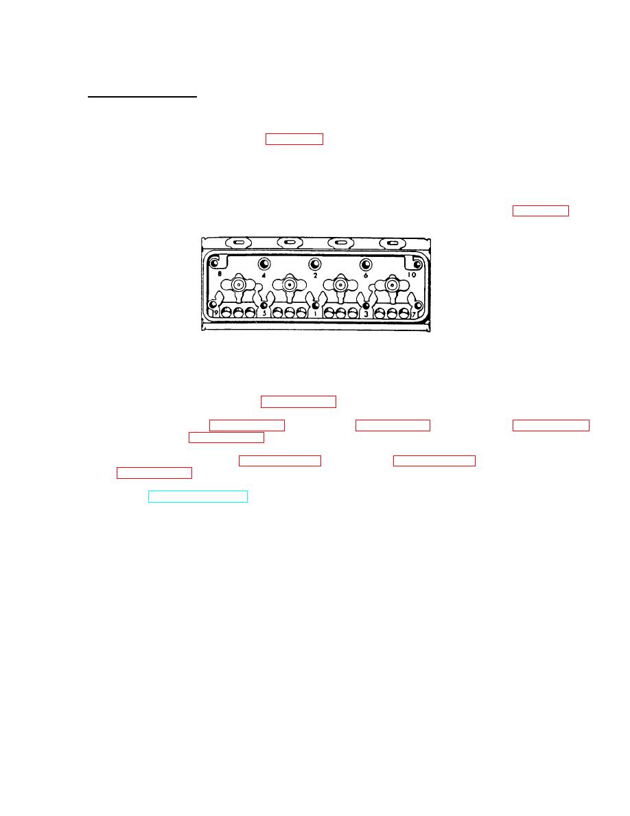
Figure 3-78. Cylinder Head Bolt Tightening Sequence. |
|
||
| ||||||||||
|
|
 TM 55-1930-208-24
3-38. HEAD, CYLINDER - Continued.
b.
Installation - Continued.
(9)
Slowly lower the cylinder head (5) into position.
(10) Apply sealing compound (item 22, Appendix C) to all cylinder head bolts (4) and nuts (3).
(11) Install ten bolts (4) and two nuts (3). Remove hoist.
(12) Remove sling from cylinder head.
(13) Torque bolts and nuts to 175-185 lb-ft (238-251 Nm) in 50 lb-ft (68 Nm) increments per figure 3-78.
Figure 3-78. Cylinder Head Bolt Tightening Sequence.
(14) Install four lockwashers (2) and four bolts (1).
(15) Install fuel injector control rack (paragraph 3-35).
(16) Install fuel injectors (paragraph 3-35), rocker cover (paragraph 3-31), water manifold (paragraph 3-27),
and thermostat (paragraph 3-28).
(17) Install air inlet housing (paragraph 3-18), air cleaners (paragraph 3-18), and exhaust manifold
(18) Refer to TM 55-1930-208-10, paragraph 2-17 and add coolant to radiator.
3-136
|
|
Privacy Statement - Press Release - Copyright Information. - Contact Us |
