 |
|||
|
|
|||
|
Page Title:
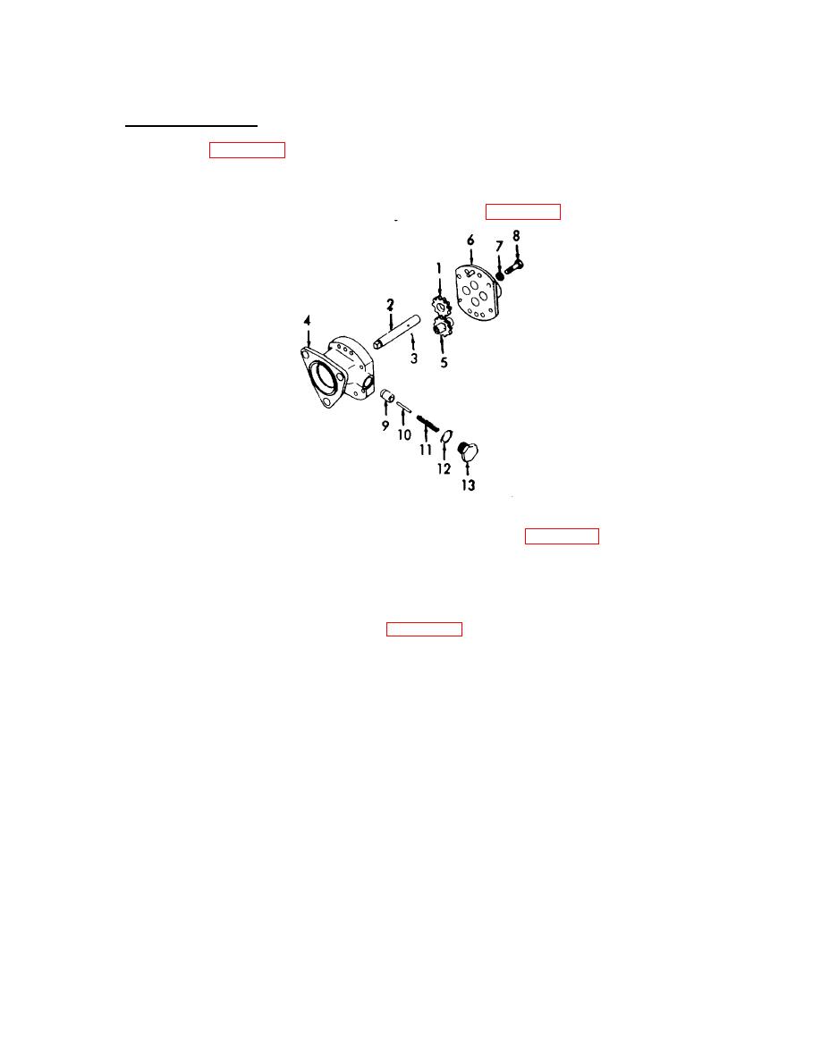
Figure 3-50. Fuel Pump, Assembly. |
|
||
| ||||||||||
|
|
 TM 55-1930-208-24
3-21. PUMP, FUEL- Continued.
f. Assembly - Continued.
(10) Refer to figure 3-50. Press the gear (1) onto the shaft (2) and beyond the ball slot.
(11) Install the steel ball (3) then press the gear back until the slot contacts the ball (3).
(12) Lubricate the pump shaft (2) with light grease (item 11, Appendix C) and install shaft to body (4).
Figure 3-50. Fuel Pump, Assembly.
(13) Lubricate the driven gear shaft (5) with light grease (item 11, Appendix C) and install.
CAUTION
Use care that sealant is not squeezed into the gear compartment, otherwise damage to the gears
and shaft may result.
(14) Apply a thin coat of sealant (item 21, Appendix C) to the cover mating surface. Install cover (6)
and secure with eight lockwashers (7) and eight bolts (8).
NOTE
The coating of sealant must be extremely thin since the pump clearances have been set up on
the basis of metal-to-metal contact. Too much sealant could increase the clearances and affect
the efficiency of the pump.
(15) Install valve (9), pin (10), spring (11), gasket (12), and plug (13). Torque plug (13) to 18-22 lb-ft
(24-30 Nm).
(16) Turn pump shaft by hand to ensure the gears rotate freely.
3-80
|
|
Privacy Statement - Press Release - Copyright Information. - Contact Us |
