 |
|||
|
|
|||
|
|
|||
| ||||||||||
|
|
 TM 55-1905-223-24-4
l.
Install two guide studs into the flywheel and two in the flywheel housing.
m. Lift the generator into position so that the mounting holes in the coupling disc (27, FIGURE 3-27) and adapter (6,
CAUTION
Do not force the alignment of the generator. Move the generator from
side to side or up and down.
REPLACEMENT (FIGURE 3-26)
a. Guide the generator into the flywheel.
b. Install machine bolts (4) and lockwashers (5) through the coupling disc intothe flywheel. Torque 45 ft-lb.
c. Install machine bolts (2) and lockwashers (3) through the generator frame adapter into the flywheel housing.
Torque 35 ft-lb.
d. Remove guide studs and install remaining capscrews.
e. Remove lifting fixture from generator.
f.
Connect all electrical wiring and remove tags.
g. Test generator set by starting up.
(1)
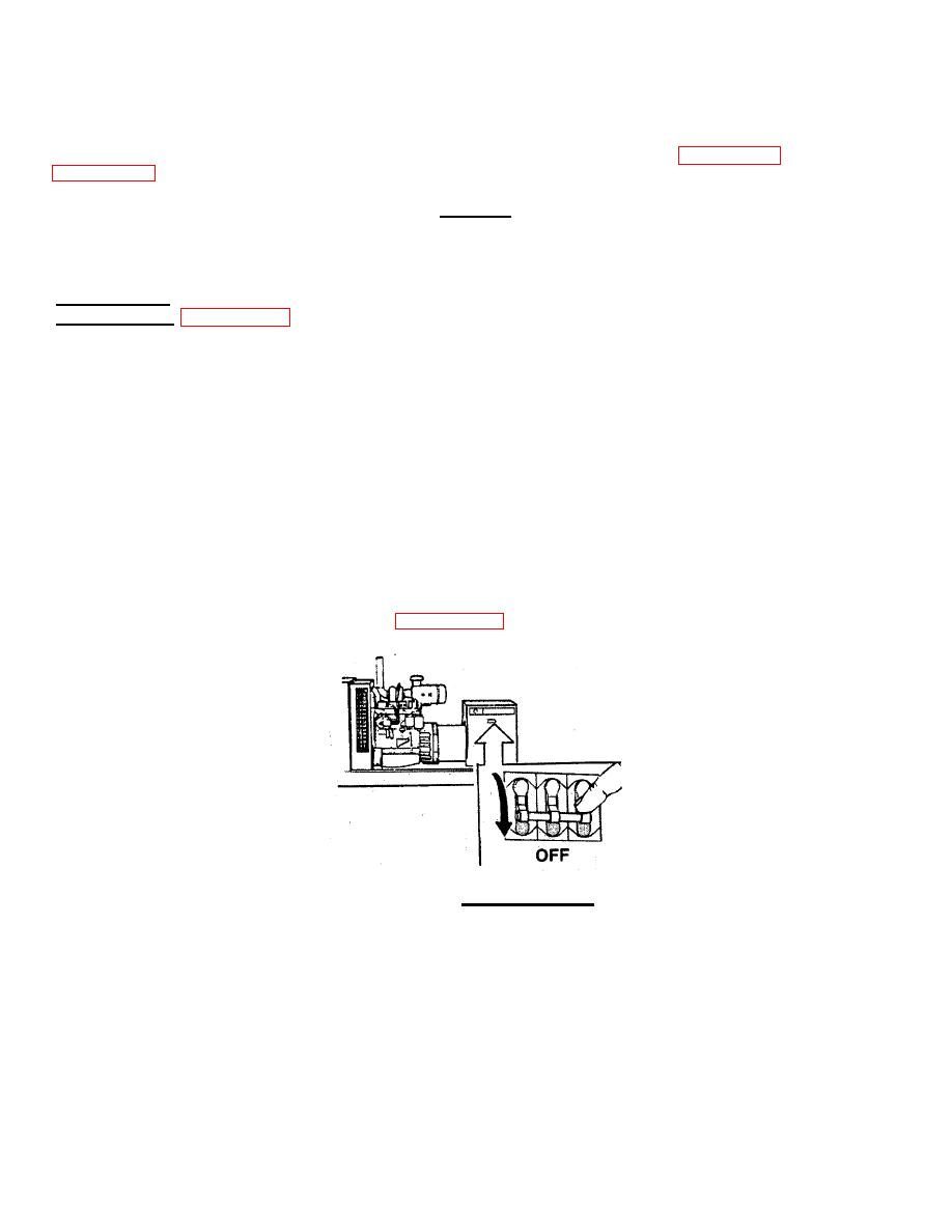
Open generator set circuit breaker. (FIGURE 3-28).
FIGURE 3-28. Set Circuit Breaker.
3-37
|
|
Privacy Statement - Press Release - Copyright Information. - Contact Us |
