 |
|||
|
|
|||
|
Page Title:
Chapter 2. OPERATING INSTRUCTIONS |
|
||
| ||||||||||
|
|
 TM 55-1740-203-13&P
CHAPTER 2
Section I. DESCRIPTION AND USE OF OPERATORS
CONTROLS AND INDICATORS
2-1. SCOPE.
This chapter describes, illustrates and furnishes the operator with in-
f o r m a t i o n pertaining to the various controls provided for operation of the
transporter.
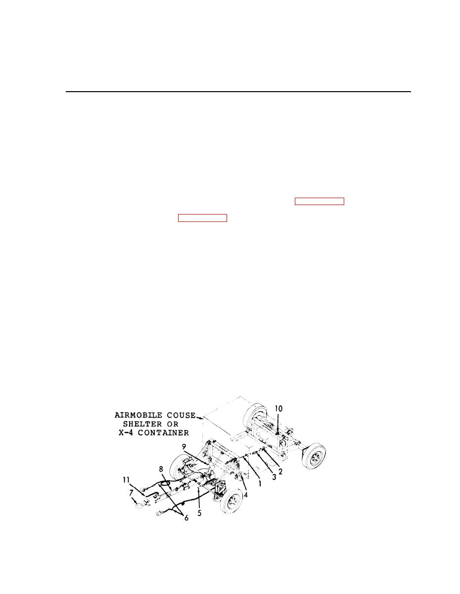
2 - 2 . CONTROLS AND INDICATORS.
(Refer to Figure 2-1).
S a f e t y cable (1) Figure 2-1 attaches to Shackles (2) on transporter
a.
assetilies and is tightened by adjusting both turnbuckles (3) .
Eye brackets (4) hold Airmobile Couse Shelter in place using bolt
b.
and lanyard assembly on Airmobile Couse Shelter.
Parking brake lever (5) controls brakes on front transporter.
c.
Safety chains (6) attach to towing vehicle.
d.
e.
L u n e t t e eye (7) on towbar (8) attaches to pintle hook of towing
vehicle.
Hydraulic jack handles (9) are used to pump jacks to raise shelter
f.
to travel configuration.
Clamps (10) on frame are used to stow the hardware used to connect
g.
the front and rear frames together when not carrying a payload.
Brake safety chain (11) is attached to towing vehicle.
h.
Figure 2-1.
Controls and Indicators.
2-1
|
|
Privacy Statement - Press Release - Copyright Information. - Contact Us |
