 |
|||
|
|
|||
|
Page Title:
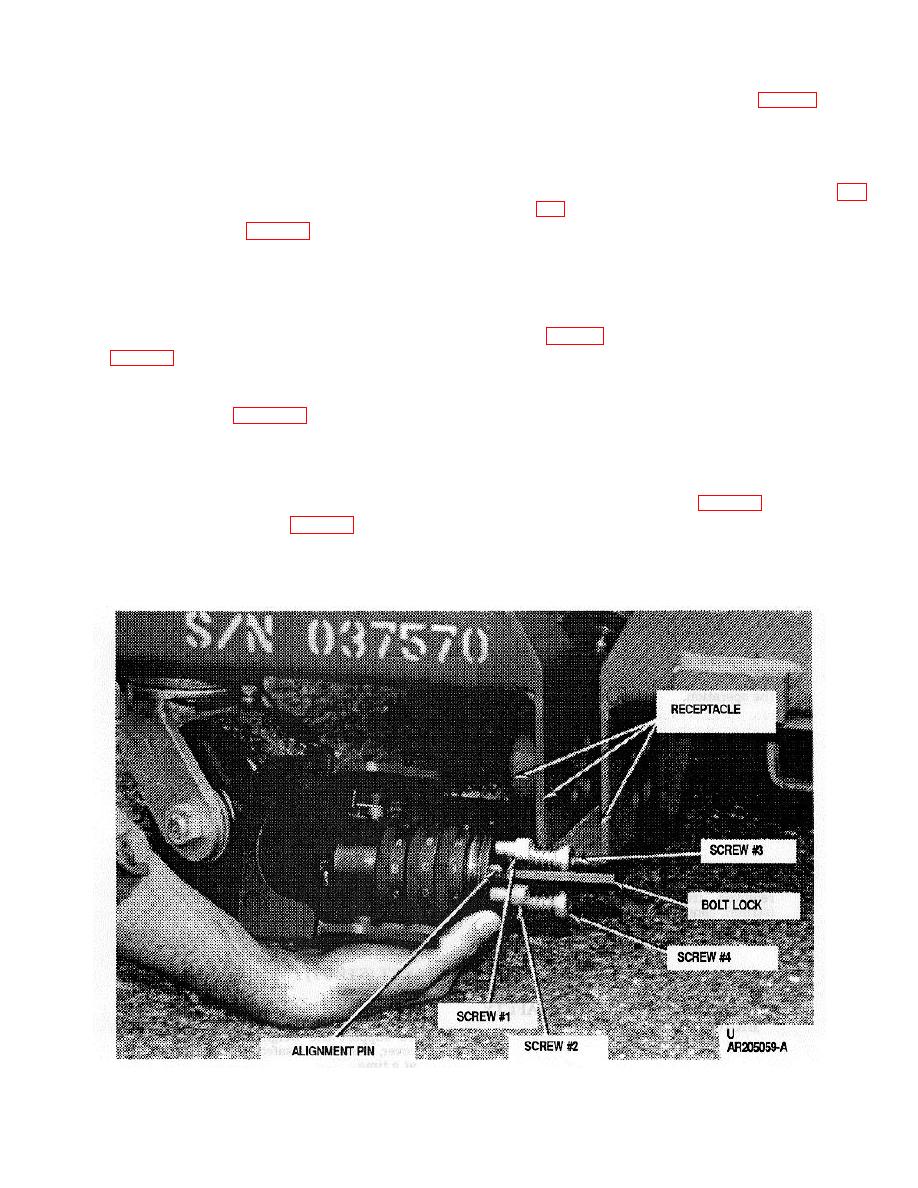
Figure 2-4. Installing Locking Devices. |
|
||
| ||||||||||
|
|
 TM 9-8140-381-14&P
2-13.
LOCKING DEVICE
f. Install second cap screw (No. 2 fig. 2-4) in hole
INSTALLATION/REMOVAL
at forward, right side of tang receptacle.
Thread approximately two turns into lock using a
5/16-inch allen wrench.
a. Lock installation requires a 5/16-inch allen
wrench socket, 1/4-inch allen wrench socket,
and flashlight.
g. Install one shoulder screw and spring (No. 3 fig.
Use 1/4-inch allen wrench.
Thread screw
b. Raise cover of cage (par. 1-6).
approximately two turns into lock with allen
wrench by simultaneously compressing spring
c. Record the three-letter combination that is
while turning.
stamped on the mounting face of the lock with
serial number of cage.
Also, record
h. Install second shoulder screw and spring (No. 4
combination for either A or B mounting face of
cage. Verify combination by unlocking lock
1/4-inch allen wrench and flat face screwdriver.
Thread screw approximately two turns into lock
with Allen wrench receptacle by simultaneously
d. Align lock with mounting holes on left side of
compressing spring while turning.
tang receptacle (fig.
(shackle) in rectangular hole of receptacle and
i. Secure all four screws to complete lock
alignment pin of lock in its mating hole. After
installation.
bolt and pin are aligned, push lock against
receptacle and hold in place with one hand.
j. Close and secure cage (par. 1-7).
e. Install cap screw (No. 1 fig. 2-4) in hole at
forward, right side of tang receptacle. Thread
k. To remove locking device, open cage and
approximately two turns into lock using a 5/16-
loosen the four screws and withdraw lock in
inch allen wrench.
reverse order (pars. d through i).
Figure 2-4. Installing Locking Devices.
2-7
|
|
Privacy Statement - Press Release - Copyright Information. - Contact Us |
