 |
|||
|
|
|||
|
|
|||
| ||||||||||
|
|
 C 1, TM 9-2920-242-35
Section II.
ASSEMBLY
d. Varnish inside of frame and coil assembly.
Leave 0.38 inch from each end of frame free of
Note. The key letters shown below in parentheses refer to
varnish. Allow varnish to dry thoroughly before
assembling starter.
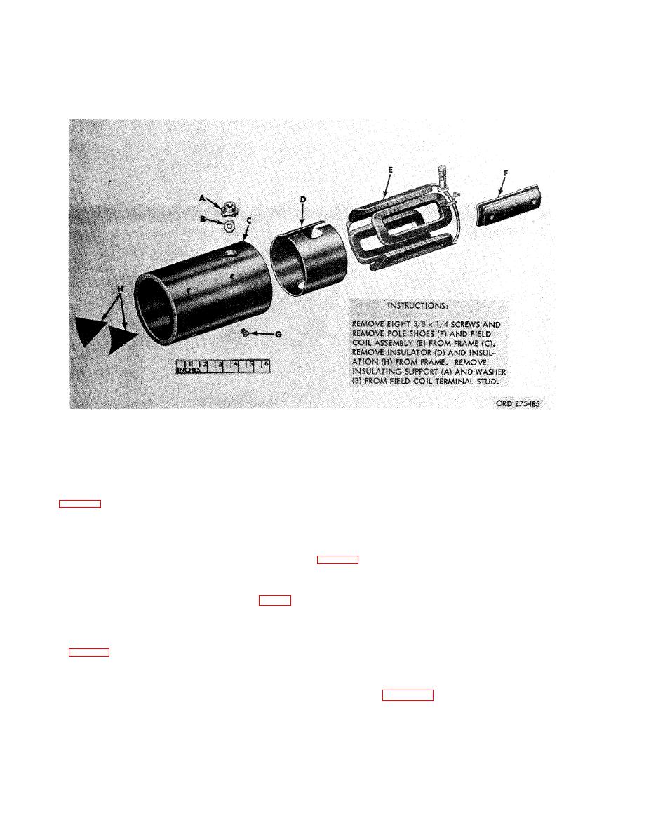
a. Install washer (B) and support, (A) on field coil
terminal stud and position field coil (E) in frame (C).
Install insulator (D) and two insulations (H)
Note. The key letters shown below in parentheses refer to
between frame and field coils.
a. Install terminal (G) on motor terminal stud (E)
b. Position each of four pole shoes (F), in turn, on
(short stud). Install motor terminal stud, battery
coil inside frame. Align mating holes and secure
terminal stud (F), terminal stud insulation strip (H),
each pole with two pole shoe screws (G) (2, fig. 56).
and terminal plate (J) with motor terminal stud in
Coat threads of pole shoe screws with a suitable
p l a t e marked MOTOR. Install one insulating
thread sealer before installation.
bushing (K), one insulator (L), one 0.516 ID.,
Note. The key letters shown below in parentheses refer
7/8 OD., 1/32 thick flat washer (M), -inch lockwasher
to figure 56.
(N), -inch, 0.312 thick hex nut (P), -inch
c. Install two nonmetallic washers (F), 0.520 ID.,
lockwasher (N) and -inch, 0.438 thick hex nut (Q)
7/8 OD., 0.031 thick flat washer (E), 1/2-inch hex nut
on each terminal stud.
(C), 1/2-inch lockwasher (B), and 1/2-inch hex nut (A).
s o l e n o i d relay.
|
|
Privacy Statement - Press Release - Copyright Information. - Contact Us |
