 |
|||
|
|
|||
|
|
|||
| ||||||||||
|
|
 surface of the commutator with
a
power-driven
undercutting
tool (fig. 34).
If a power-
driven tool is not available,
the mica may be undercut by hand,
Should small burs extend be-
yond the grooves, they can be
removed by running a three-cor-
nered scraper along the bottom
edge of the groove.
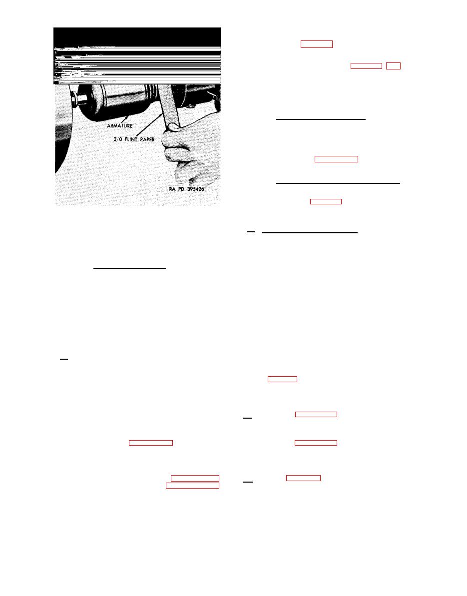
Polishing
commutator.
After
(3)
the mica has been undercut, re-
move all copper and mica par-
ticles with compressed air.
Polish the commutator in a lathe
2/0 sandpaper as illus-
with
trated in figure 36, with the
armature rotating at 1500 rpm.
Checking armature eccentricity.
(4)
Setups dial indicator gage and
measure the runout of the com-
mutator (fig. 31). Total run-
out should not exceed 0.003-
inch.
Polishing commutator
with sandpaper.
f. Insulating Field Coils.
Apply as
many coats of insulating varnish as neces-
Note. When a cut is started,
sary to properly insulate the field coils.
it should be carried across en-
Allow each coat to dry Until "tacky" before
tire surface without stopping.
applying another coat.
After sufficient
After re-
coats have been applied, place the field
(2)
Undercutting mica.
coils in a drying oven and bake for two
surfacing the armature, under-
hours at a temperature of 193F (77C).
cut mica to l/32-inch below the
Section IV.
ASSEMBLY
28. General
of the starter and for part identification
a.
The instructions covering assembly
of the starter are almost identically the
reverse of those covering disassembly.
When one part of the brush parts kit -
Therefore, the following assembly proce-
5702664 (fig. 51) requires replacement,
dures, for the most part, will be refer-
the entire kit should be used.
enced to the illustrations appearing under
disassembly.
When this occurs, the in-
30. Brushes
structions appearing with each referenced
illustration should be performed in the
Refer to figure 25 for instructions
a.
reverse order from which they are given.
covering installation of square bushing
For example, callout letters A, B, C, and
and associated parts.
D indicate the sequence of the disassembly
b.
steps provided with figure 23.
Assembly
Refer to figure 24 for instructions
-
may be accomplished by performing these
covering installation of brushes.
i.e., D, C, B,
steps in reverse order;
and A.
a . Refer to figures 23 and 22 for in-
b.
The exploded views,
structions covering assembly of the commu-
through 50, are included in Appendix II
tator end head assembly.
of the manual to provide a visual refer-
ence to the relationship of the components
|
|
Privacy Statement - Press Release - Copyright Information. - Contact Us |
